Accommodating intraocular lens system having spherical aberration compensation and method

a technology of spherical aberration and compensating method, which is applied in the field of intraocular lenses, can solve the problems of preventing widespread commercialization of such devices, unable to accommodate, and typically already lost ability, so as to reduce the effect of refractive effects and optical aberrations, increasing the cross-sectional area of the haptic, and increasing the internal volume of the hapti

Active Publication Date: 2007-05-10
ALCON INC
View PDF98 Cites 150 Cited by
  • Summary
  • Abstract
  • Description
  • Claims
  • Application Information

AI Technical Summary

Benefits of technology

[0029] The haptic portion is disposed at the periphery of the optic portion and comprises one or more haptics that extend outward from the optic portion, each haptic including a fluid channel coupled in fluid communication with a fluid channel in the optic portion. In accordance with one aspect of the present invention, the haptics have a cross-sectional configuration selected so that the internal volume of the haptic is small in an accommodated state. The accommodated state of the haptic is selected to correspond to the accommodated state of the eye, when the ciliary muscles are contracted and anterior / posterior compressive forces applied by the capsular bag to the haptics are reduced.
[0030] When the ciliary muscles relax, the zonules pull the capsular sac taut and apply forces to the anterior and posterior faces of the haptic. The forces applied by the capsular sac cause the cross-sectional area of the haptic to increase thereby increasing the internal volume of the haptic. This action in turn causes fluid to be withdrawn from the actuator disposed in the optic portion, so that the dynamic surface of the IOL transitions from an accommodated state to an unaccommodated state. The fixed volume of shaping fluid in the sealed fluid cavity is redistributed in the cavity by movement of the dynamic surface and that redistribution causes the shape of the dynamic surface to be altered.
[0031] The actuator used in the optic portion of the IOL may be centrally located within the optic portion that, when filled with fluid, biases the dynamic surface of the IOL to the accommodated state. When the ciliary muscles are contracted, the zonules and capsular bag are less taut, and the haptics are unstressed. Relaxation of the ciliary muscle causes the zonules to transition the capsule to less convex shape, which applies compressive forces to the haptic, thereby withdrawing fluid from the actuator and causing the lens to transition to the unaccommodated state. Alternatively, the actuator may comprise structures disposed at the periphery of the optic portion, so as to further minimize refractive effects and optical aberrations in the optic portion.

Problems solved by technology

Since the lens can no longer accommodate, however, the patient typically needs glasses for reading.
After placement, accommodation is no longer possible, although this ability is typically already lost for persons receiving an IOL.
Although previously known workers in the field of accommodating IOLs have made some progress, the relative complexity of the methods and apparatus developed to date have prevented widespread commercialization of such devices.
Previously known devices have proved too complex to be practical to construct or have achieved only limited success, due to the inability to provide accommodation of more than 1-2 diopters.
According to Eyeonics, redistribution of the ciliary mass upon constriction causes increased vitreous pressure resulting in forward movement of the lens.
Another disadvantage of previously known devices is that they oftentimes create spherical aberrations.
As is well known in the art, lenses composed of elements having spherical surfaces are easy to manufacture but are not ideal for creating a sharp image because light passing through the elements does not focus on a single focal point.
As a result of spherical aberration in an intraocular lens, all of the light passing through the lens does not focus on the retina resulting in an image that may be blurred and may have softened contrast.
Such a device provides an obvious disadvantage that the amount of light allowed to pass through the lens is reduced.
However, such combined lenses and lenses having aspherical profiles are significantly more expensive to produce.
In addition, combining lenses requires additional space to house the multiple lenses.

Method used


Image

  • Accommodating intraocular lens system having spherical aberration compensation and method
  • Accommodating intraocular lens system having spherical aberration compensation and method
  • Accommodating intraocular lens system having spherical aberration compensation and method

Examples


Embodiment Construction

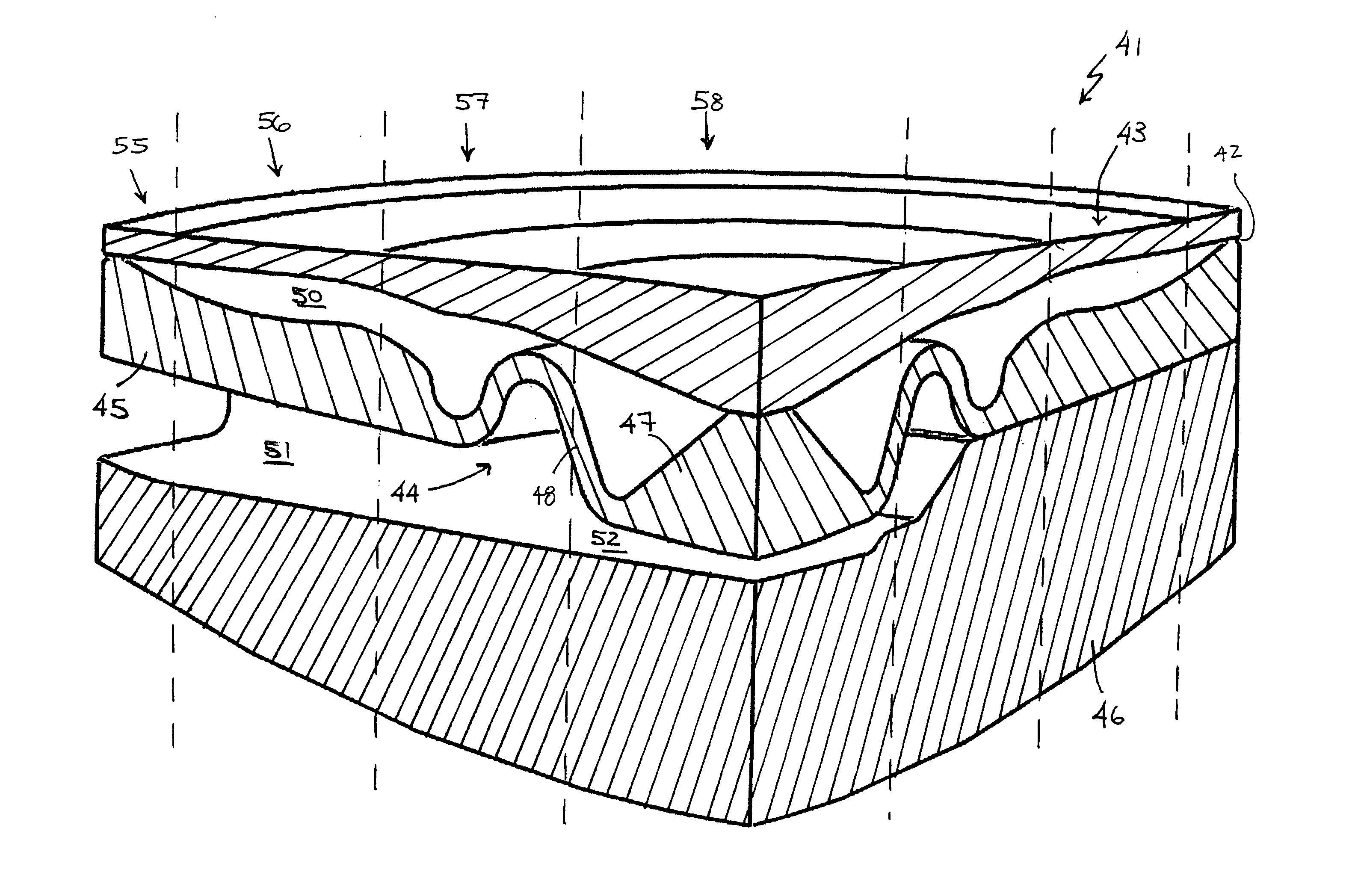
[0046] In accordance with the principles of the present invention, an intraocular lens is provided having a haptic portion and a light-transmissive optic portion. The optic portion contains one or more fluid-mediated actuators arranged to apply a deflecting force on a dynamic surface of the lens to provide accommodation. As used herein, the lens is fully “accommodated” when it assumes its most highly convex shape, and fully “unaccommodated” when it assumes its most flattened, least convex state. The lens of the present invention is capable of dynamically assuming any desired degree of accommodation between the fully accommodated state and fully unaccommodated state responsive to movement of the ciliary muscles and lens capsule.

[0047] Furthermore, in accordance with the principles of the present invention the optic portion contains one or more secondary deflection mechanism that alters the curvature of the lens. For example, the secondary deflection mechanism may be sealed fluid cav...


PUM


Abstract

An accommodating intraocular lens includes an optic portion, a haptic portion. The optic portion of the lens includes an actuator that deflects a lens element to alter the optical power of the lens responsive to forces applied to the haptic portion of the lens by contraction of the ciliary muscles and a secondary deflection mechanism. Movement of the lens element by the actuator causes the lens element to deform and the secondary deflection mechanism causes the lens to further deform.

Description

REFERENCE TO RELATED APPLICATIONS [0001] This application is a continuation-in-part of U.S. patent application Ser. No. 10 / 971,598, filed Oct. 22, 2004, which is a continuation-in-part of U.S. patent application Ser. No. 10 / 734,514, filed Dec. 12, 2003, and claims the benefit of priority from U.S. provisional patent application Ser. No. 60 / 433,046, filed Dec. 12, 2002, the disclosures of which are hereby incorporated by reference in their entirety.FIELD OF THE INVENTION [0002] The present invention relates to intraocular lenses (“IOLs”) having optical parameters that are changeable in-situ. More particularly, the invention has application in IOLs for in-capsule implantation for cataract patients or presbyopic patients, wherein movement of the lens capsule applies forces to a circumferentially supported haptic to more efficiently induce transfer of fluid media within the interior of the IOL to alter an optical power of the lens. BACKGROUND OF THE INVENTION [0003] Cataracts are a majo...

Claims


Application Information

Patent Timeline
Patent Type & Authority Applications(United States)
IPC IPC(8): A61F2/16
CPCA61F2/1613A61F2250/0053A61F2/1637A61F2/1635A61F2002/1681
Inventor SMITH, DAVID JOHNSMILEY, TERAH WHITINGSCHOLL, JOHN A.BURNS, DENISE HORRILLENOESCH, VICTOR
Owner ALCON INC
Why Eureka
Try Eureka