Methods and systems to accurately display lateral deviation symbology in offset approaches to runways

a technology of offset approaches and symbols, applied in the field of aircraft navigation instruments, to achieve the effect of accurately displaying lateral deviation symbols

Active Publication Date: 2007-05-10
HONEYWELL INT INC
View PDF11 Cites 42 Cited by
  • Summary
  • Abstract
  • Description
  • Claims
  • Application Information

AI Technical Summary

Benefits of technology

[0006] The Embodiments of the present invention provide methods and systems for to accurately display lateral dev

Problems solved by technology

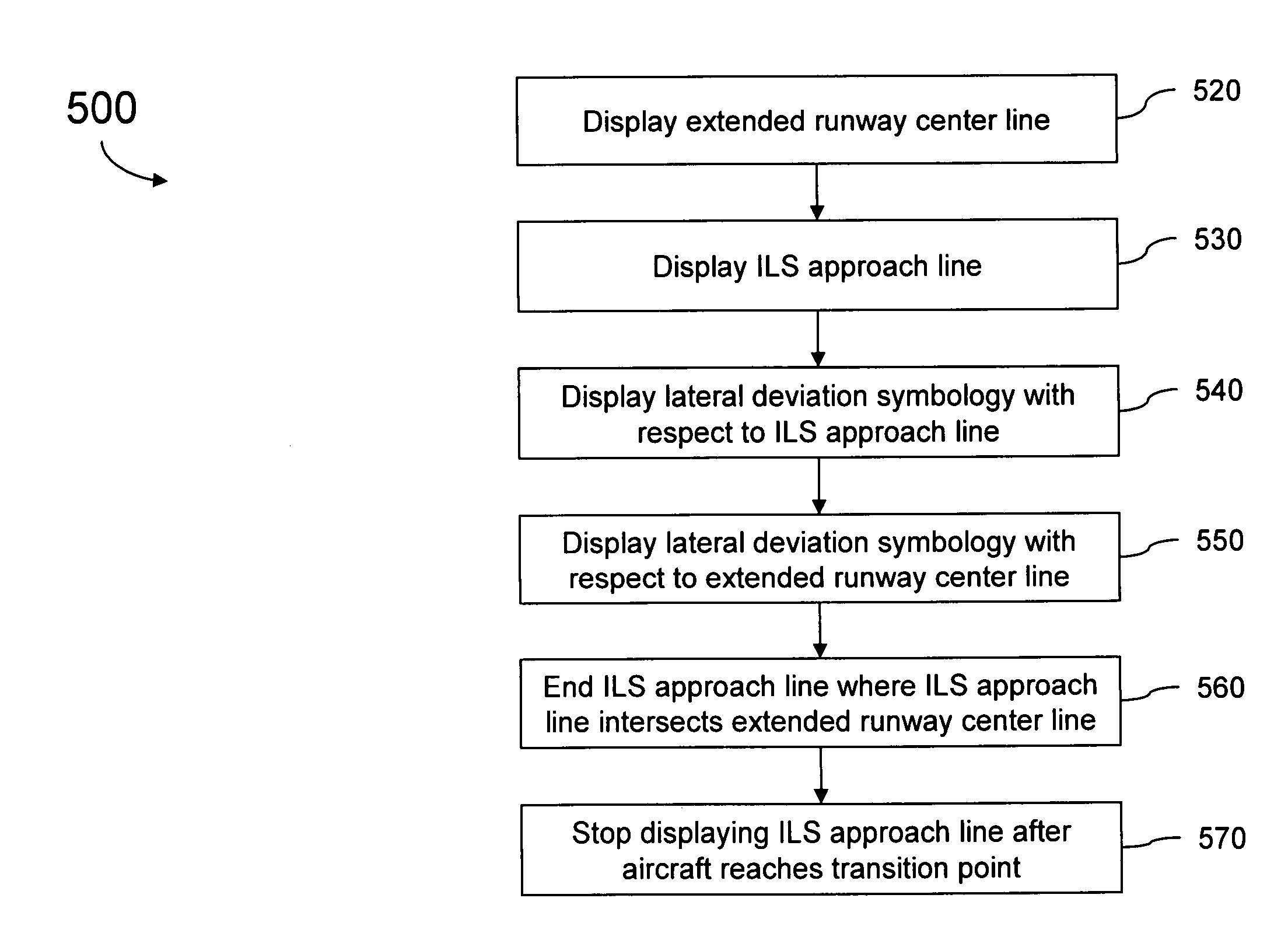
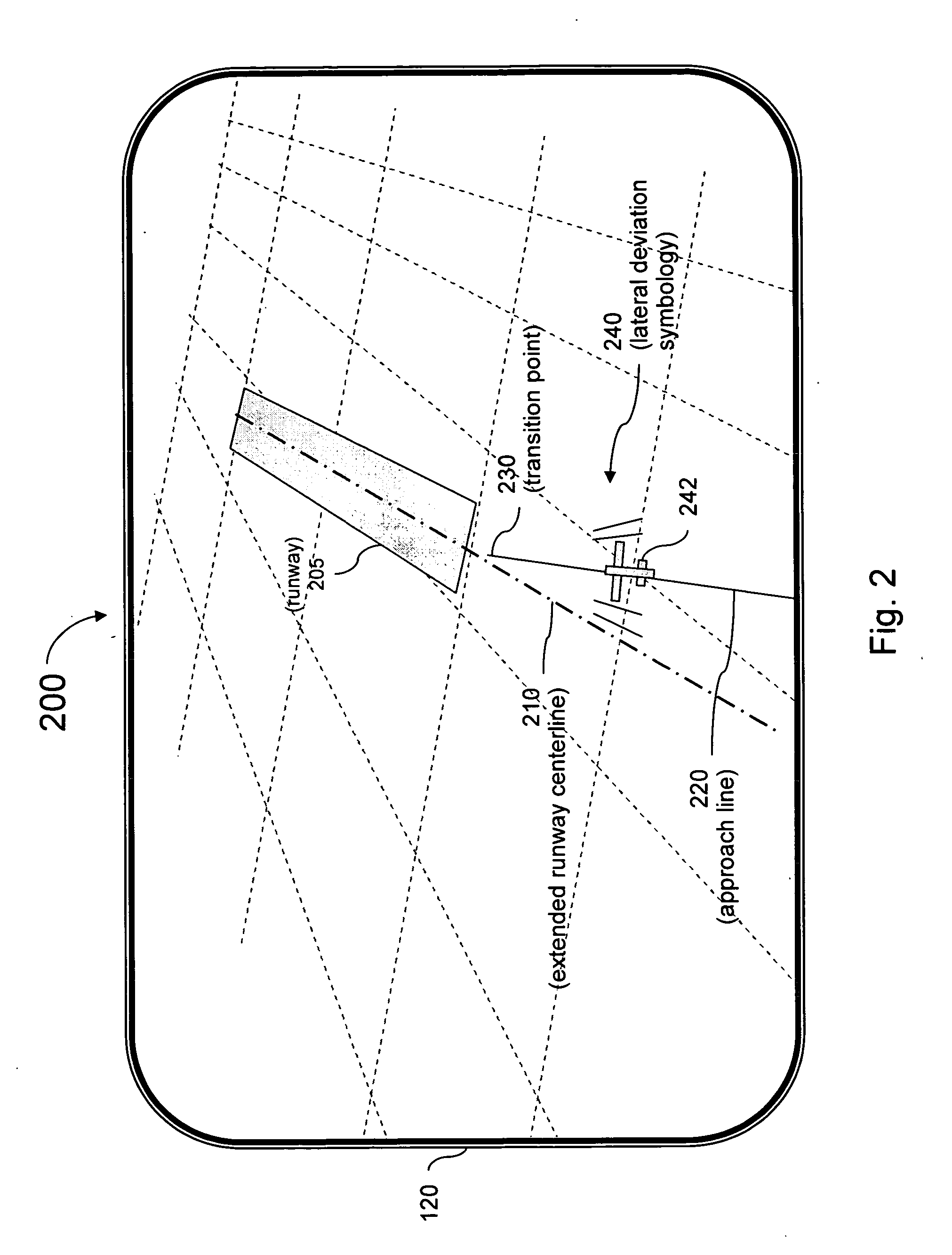
This misalignment between the runway centerline direction and the ILS approach line direction creates difficulties when displaying information for such an approach on high resolution symbolic visual display systems, such a

Method used


Image

  • Methods and systems to accurately display lateral deviation symbology in offset approaches to runways
  • Methods and systems to accurately display lateral deviation symbology in offset approaches to runways
  • Methods and systems to accurately display lateral deviation symbology in offset approaches to runways

Examples


Embodiment Construction

[0019] In the following detailed description, reference is made to the accompanying drawings that form a part hereof, and in which is shown by way of illustration specific illustrative embodiments in which the invention may be practiced. These embodiments are described in sufficient detail to enable those skilled in the art to practice the invention, and it is to be understood that other embodiments may be utilized and that logical, mechanical and electrical changes may be made without departing from the scope of the present invention. The following detailed description is, therefore, not to be taken in a limiting sense.

[0020] Although the examples of embodiments in this specification are described in terms of the currently widely used ILS, embodiments of the present invention are not limited to applications of airports utilizing ILS. To the contrary, embodiments of the present invention are applicable to any runway utilizing a runway assistance landing system (of which ILS is an e...


PUM


Abstract

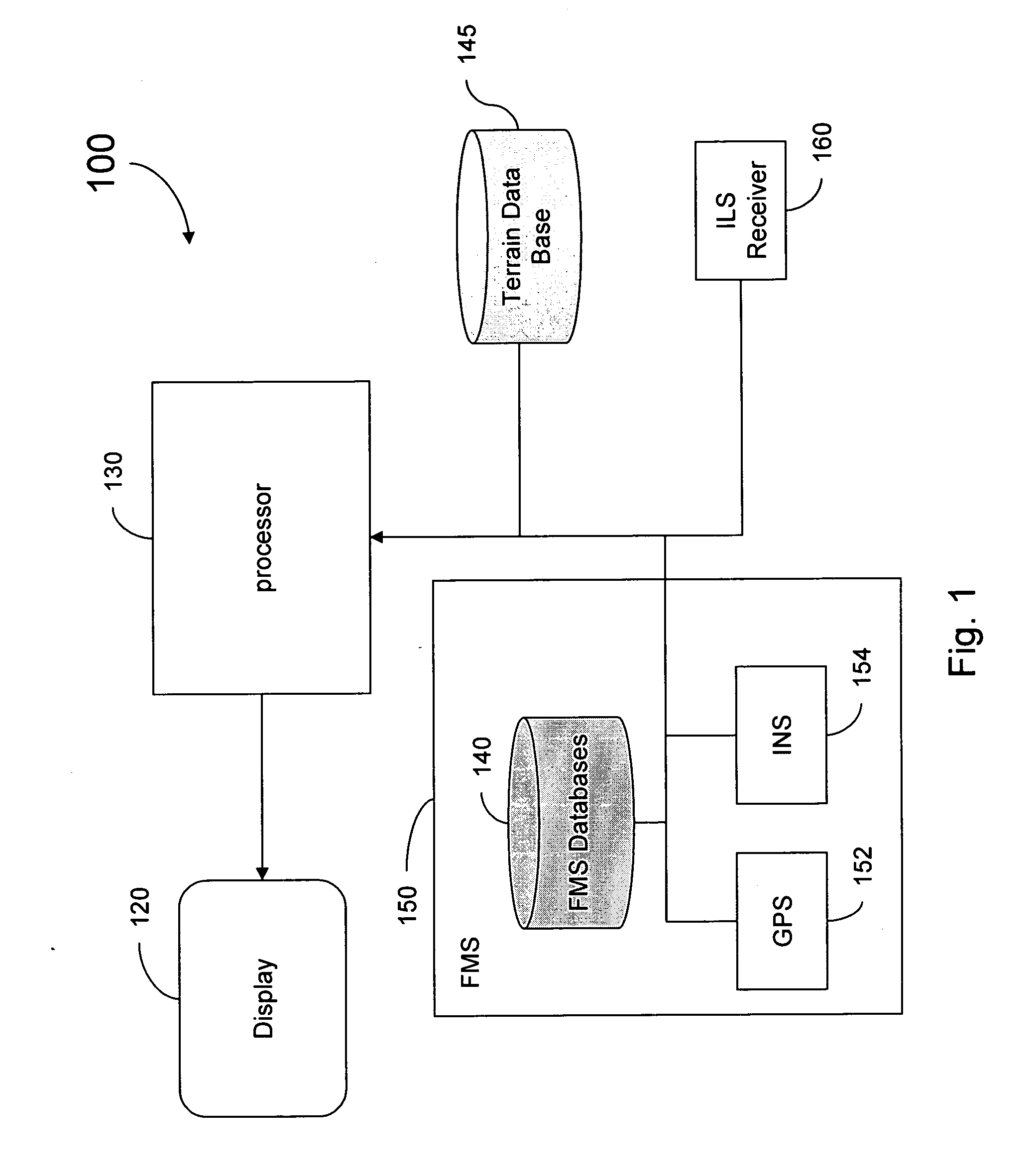
Systems and methods to accurately display lateral deviation symbology in offset approaches to runways is provided. A system for on-aircraft display of lateral deviation symbology for use in offset approaches comprises means for generating a conformal video display representation of an aircraft's current position, means for notifying a flight crew of the existence of an offset approach, means for displaying an extended runway center line, and means for displaying an approach line.

Description

TECHNICAL FIELD [0001] The present invention generally relates to aircraft navigation instrumentation and more specifically to displaying lateral deviation symbology. BACKGROUND [0002] The primary approach system used by most airports is the Instrument Landing System (ILS). ILS facilities provide an accurate and dependable means of navigating an aircraft to most runways for landing. An ILS transmits narrow horizontal beams which let flight crews know if their aircraft is left, right, or directly on course for a runway. The signal transmitted by the ILS consists of two vertical fan-shaped beam patterns that overlap at the center. Ideally, the beams are aligned with the extended centerline of the runway. The right side beam is typically referred to as the “blue” area while the left side of beam is the “yellow” area. An overlap between the two beams provides an on-track signal to aircraft. Ideally, at the point where ILS receivers on the aircraft receive blue area and yellow area beams...

Claims


Application Information

Patent Timeline
IPC IPC(8): G01C23/00
CPCG01C23/005G08G5/0021G08G5/025G08G5/02
Inventor HE, GANG
Owner HONEYWELL INT INC
Why Eureka
Try Eureka