Modular hinge for handheld electronic devices

Active Publication Date: 2007-05-17
RPX CORP
View PDF14 Cites 23 Cited by
  • Summary
  • Abstract
  • Description
  • Claims
  • Application Information

AI Technical Summary

Benefits of technology

[0019] Embodiments of the present invention solve the above-identified problems by providing a handheld electronic device comprising two portions with a hinge mechanism therebetween. The hinge mechanism functions such that the two portions can be articulated into a plurality of different relative configurations. The hinge is a modular hinge which allows for the creation of many different single or multi-axis hinges using the same basic set of hinging elements arranged in different configurations in conjunction with purpose design metal bracketry. The concept allows for hinges to be supplied ready fitted with interconnection wiring.
[0020] The concept allows very quick design of hinges to meet a whole range of articulation requirements. Also it limits the need for extensive testing on every new hinge, as the hinge will be made of proven hinge elements. The design allows for multi-access rotation.
[0021] Another major benefit of embodiments of the present invention is that a path is provided inside the hinge mechanism

Problems solved by technology

A problem with known handheld electronic devices is providing a device which is small enough to be carried about by a user, while being large enough to incorporate essential features of the device for operation.
Another problem with known handheld electronic devices is that they have become so small that they are difficult to hold, manipulate and operate.
In particular, they are difficult to both hold and operate at the same time.
Another problem with known handheld electronic devices is that of operating buttons on the device by accident while carrying the device around.
The device may also be damaged while being carried around.
For example, a screen of the device may be scratched or broken.
A further problem more specific to mobile phone devices is that they have become so small that in use they no longer cover the mouth and ear of the user at the same time.
That is, ear-mouth coverage is poor due to the smaller size of modern devices.
This can lead to poor sound quality for both caller a

Method used


Image

  • Modular hinge for handheld electronic devices
  • Modular hinge for handheld electronic devices
  • Modular hinge for handheld electronic devices

Examples


first embodiment

[0051] a hinge module according to the present invention will now be described with reference to FIGS. 5 to 8.

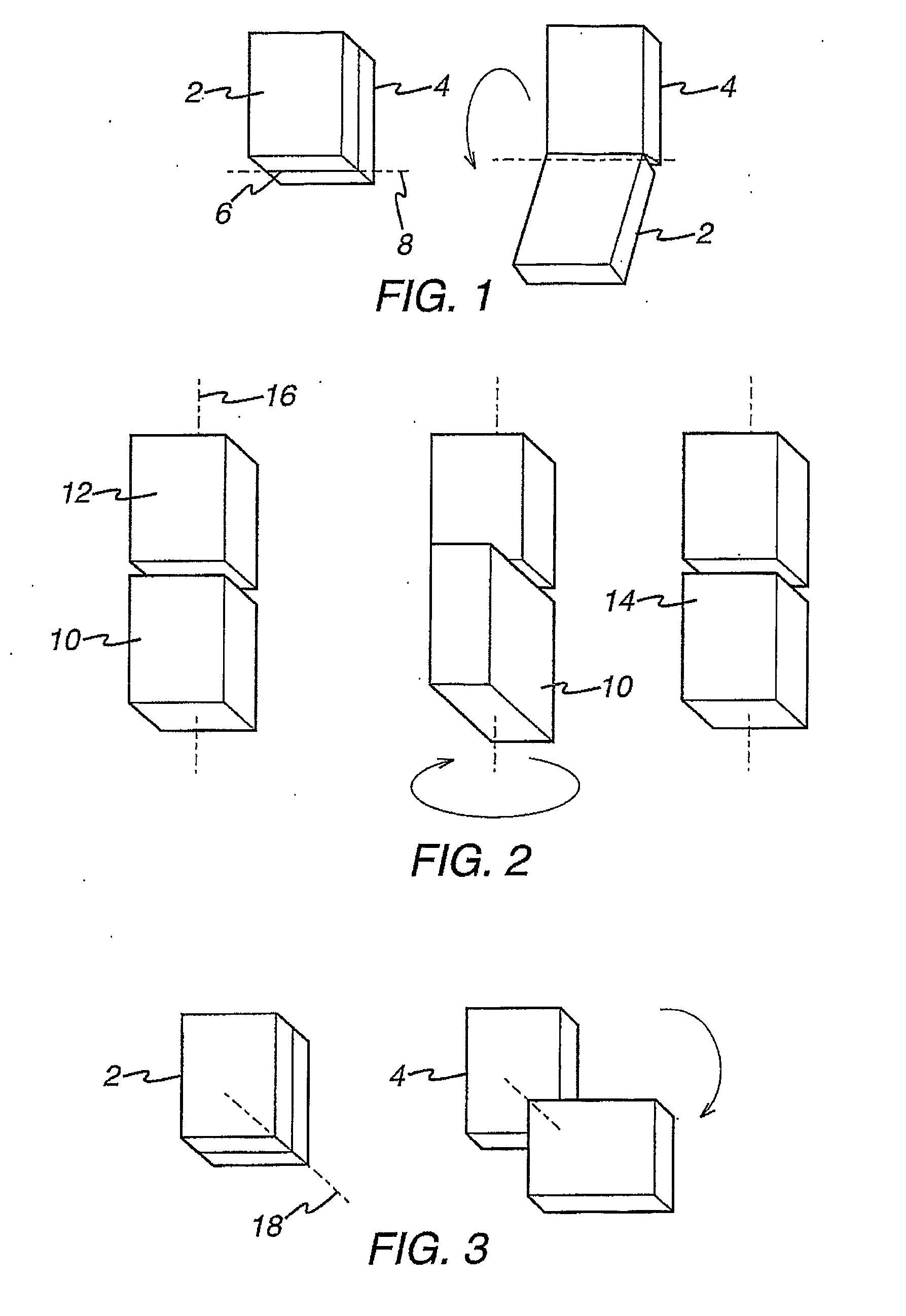
[0052]FIG. 5 shows a first embodiment of a product according to the present invention which can undergo a flip-type motion as illustrated in FIG. 1. The illustrated embodiment can fold though a full 360°. The product 40 comprises a first body portion 42 comprising two covers, a second body portion 44 comprising two covers and a hinge module 46 connecting the first and second portions. In an alternative embodiment the body portions each comprise a single cover.

[0053]FIG. 6 shows a partial cutaway view of the embodiment shown in FIG. 5. The hinge module comprises four arms 22, four bosses 24, four c-clips 32, one H-shaped bracket 48, two covers 50, four springs 26, and four washers 28. The parts are arranged into four hinge elements as previously described and shown in FIG. 4, the four hinge elements being connected together via a H-shaped bracket. The H-shaped bracket compri...

second embodiment

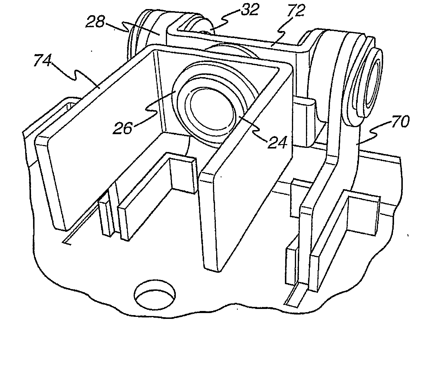
[0058]FIG. 9 shows a product 60 according to the present invention which can undergo flip and twist motions as illustrated in FIGS. 1 and 2. The product comprises a first body portion 62 comprising two covers, a second body portion 64 comprising two L-shaped covers 64a, 64b, and a hinge module 66 connecting the first and second portions. The two L-shaped covers 64a, 64b of the second body portion form an L-shaped body portion with a portion 68 which extends perpendicular to the first body portion 62 across the width of the first body portion. The hinge module is disposed between this perpendicular portion and the first body portion. A pair of covers is provided for housing the complete hinge module to prevent dust and other debris getting into the mechanism.

[0059]FIG. 10 shows a partial cutaway view of the embodiment shown in FIG. 9. This hinge module comprises two covers, three bosses, one C-shaped bracket 72, three C-clips, two L-shaped arms 70, three springs, one U-shaped bracket...

third embodiment

[0063]FIG. 12 shows a product 80 according to the present invention which can undergo a flip, twist and sidewind motion as illustrated in FIGS. 1 to 3. The product comprises a first body portion 82 comprising two covers, a second body portion 84 comprising two covers, and a hinge module 86 connecting the first and second portions. Four covers are provided for housing the complete hinge module to prevent dust and other debris getting into the mechanism.

[0064]FIG. 13 shows a partially cutaway view of the embodiment shown in FIG. 11 comprising a number of hinge elements as shown in FIG. 4. This hinge module comprises four arms, five bosses, two c-brackets, five c-clips, five springs and five washers. The parts are arranged into five hinge elements as previously described and shown in FIG. 4, the five hinge elements being connected together via two C-brackets. The C-brackets each comprise a cross-piece and two lobes, each lobe and each cross-piece having a circular cut away portion for ...


PUM


Abstract

A modular hinge for mechanically connecting first and second parts of a handheld electronic device, said modular hinge comprising at least two hinge elements, each hinge element comprising an arm and a boss with a through hole for receiving wiring for electrically connecting the first and second parts, said arm being rotatably mounted on said boss, and wherein the hinge elements are mounted on a bracket with said through holes in alignment.

Description

FIELD OF INVENTION [0001] The present invention relates to a hinge for a handheld electronic device. Particularly but not exclusively, the present invention relates to a hinge for a mobile phone. BACKGROUND OF THE INVENTION [0002] A problem with known handheld electronic devices is providing a device which is small enough to be carried about by a user, while being large enough to incorporate essential features of the device for operation. [0003] Another problem with known handheld electronic devices is that they have become so small that they are difficult to hold, manipulate and operate. In particular, they are difficult to both hold and operate at the same time. [0004] Another problem with known handheld electronic devices is that of operating buttons on the device by accident while carrying the device around. The device may also be damaged while being carried around. For example, a screen of the device may be scratched or broken. [0005] A further problem more specific to mobile p...

Claims


Application Information

Patent Timeline
IPC IPC(8): E05D3/10E05D3/06H04M1/02
CPCE05D3/10E05D3/12E05Y2900/606H04M1/0212H04M1/022G06F1/1616G06F1/1681H04M1/0206H04M1/02H04B1/38
Inventor BARNETT, RICKY
Owner RPX CORP
Why Eureka
Try Eureka