Distributed Pressure Sensoring System

a sensoring system and distribution pressure technology, applied in the direction of fluid pressure measurement, measurement devices, instruments, etc., can solve the problem that devices typically cannot measure pressur

Inactive Publication Date: 2007-05-17
GALEWSKI CARL JOHAN
View PDF6 Cites 22 Cited by
  • Summary
  • Abstract
  • Description
  • Claims
  • Application Information

AI Technical Summary

Benefits of technology

[0013] In one embodiment, the system further includes a monitoring station coupled to the sensors by wiring. In another embodiment where the sensors include wireless transmission capability, the monitoring station the system further includes a monitoring station coupled to the se

Problems solved by technology

However, those gauges are most-often mounted externally to the process chamber and may only measure conditions near a workpiece.
These devices typically cannot measure pressure, for example, at specific surface point locations or small areas of a workpiece surface.
Ga

Method used


Image

  • Distributed Pressure Sensoring System
  • Distributed Pressure Sensoring System
  • Distributed Pressure Sensoring System

Examples


Embodiment Construction

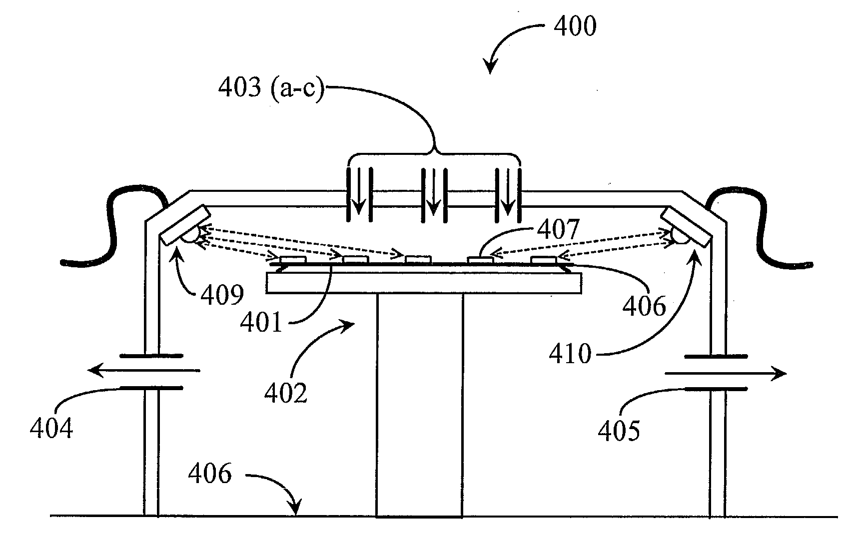
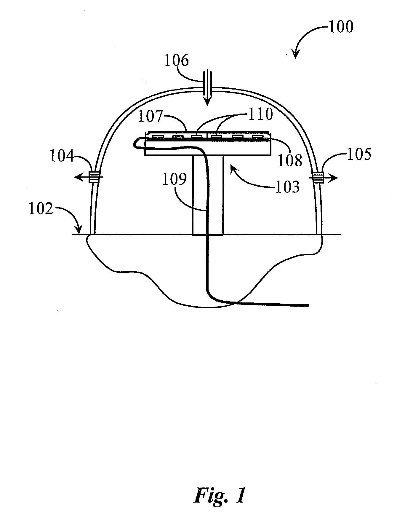
[0027]FIG. 1 is an elevation view of a process chamber 100 and pressure sensing system 108 according to an embodiment of the present invention. Chamber 100 is exemplary only and is intended here to represent generically a process chamber for implementing a gas phase process, which may be an atomic layer deposition (ALD) process in one example. Chamber 100 may be manufactured of aluminum, stainless steel, or other suitable materials for the type of process being considered. Materials acceptable in vacuum processing may include graphite, quartz glass, ceramic, and others. One important characteristic relative to the present invention is that gas pressure inside the chamber is an important variable to success in the particular process conducted within the chamber. Local pressure is typically an important variable related to both the flow and rate at that point. This importance dictates the exact deposition processes that the invention applies to, one of which may be ALD. It is importan...


PUM


Abstract

A system is provided for sensing and monitoring pressure conditions and variations over an actual or represented surface area of a workpiece in a process chamber. The system includes a substrate and a plurality of micro-electrical-mechanical-systems (MEMS) pressure sensors fixed to the substrate.

Description

CROSS-REFERENCE TO RELATED APPLICATIONS [0001] The present invention claims priority to a U.S. provisional patent application Ser. No. 60 / 732,244 entitled “Pressure Distribution Monitor” filed on Oct. 31, 2005. The referenced application is included herein at least by reference.BACKGROUND OF THE INVENTION [0002] 1. Field of the Invention [0003] The present invention is in the field of gas phase processing, and pertains particularly to methods and apparatus for measuring local pressure values inside process chambers. [0004] 2. Discussion of the State of the Art [0005] The technique of gas phase processing is commonly used in large-scale manufacturing to deposit or remove layers from workpieces. The technique typically involves exposing a workpiece to a gaseous ambient of controlled composition and pressure in a process chamber with the addition of some form of energy such as temperature or radio frequency (RF) to induce a reaction to occur between the gaseous ambient and the workpiec...

Claims


Application Information

Patent Timeline
IPC IPC(8): G01L9/00
CPCG01L9/0052G01L9/0072G01L19/086
Inventor GALEWSKI, CARL JOHAN
Owner GALEWSKI CARL JOHAN
Why Eureka
Try Eureka