Battery cell for MEMS device and related methods

a battery cell and mems technology, applied in the field of micro electricalmechanical systems, can solve the problems of not being desirable, convenient or feasible to draw power from an external source, not being desirable, and consuming a large percentage of the available space on the silicon substrate, etc., to achieve the effect of long li

Active Publication Date: 2011-04-28
HARRIS CORP
View PDF14 Cites 17 Cited by
  • Summary
  • Abstract
  • Description
  • Claims
  • Application Information

AI Technical Summary

Benefits of technology

[0012]The MEMS device may include semiconductor circuitry on the MEMS substrate coupled to the at least one MEMS structure and the at least one battery cell. In addition, there may be at least one photovoltaic cell on the MEMS substrate for charging the at least one battery cell. The in

Problems solved by technology

In some cases, it may not be desirable, convenient, or feasible to draw power from an external source.
In order for an implementation of either of these batteries to generate larger voltages, however, it may require many cells arrayed on a large percentage of the available space of

Method used


Image

  • Battery cell for MEMS device and related methods
  • Battery cell for MEMS device and related methods
  • Battery cell for MEMS device and related methods

Examples


Embodiment Construction

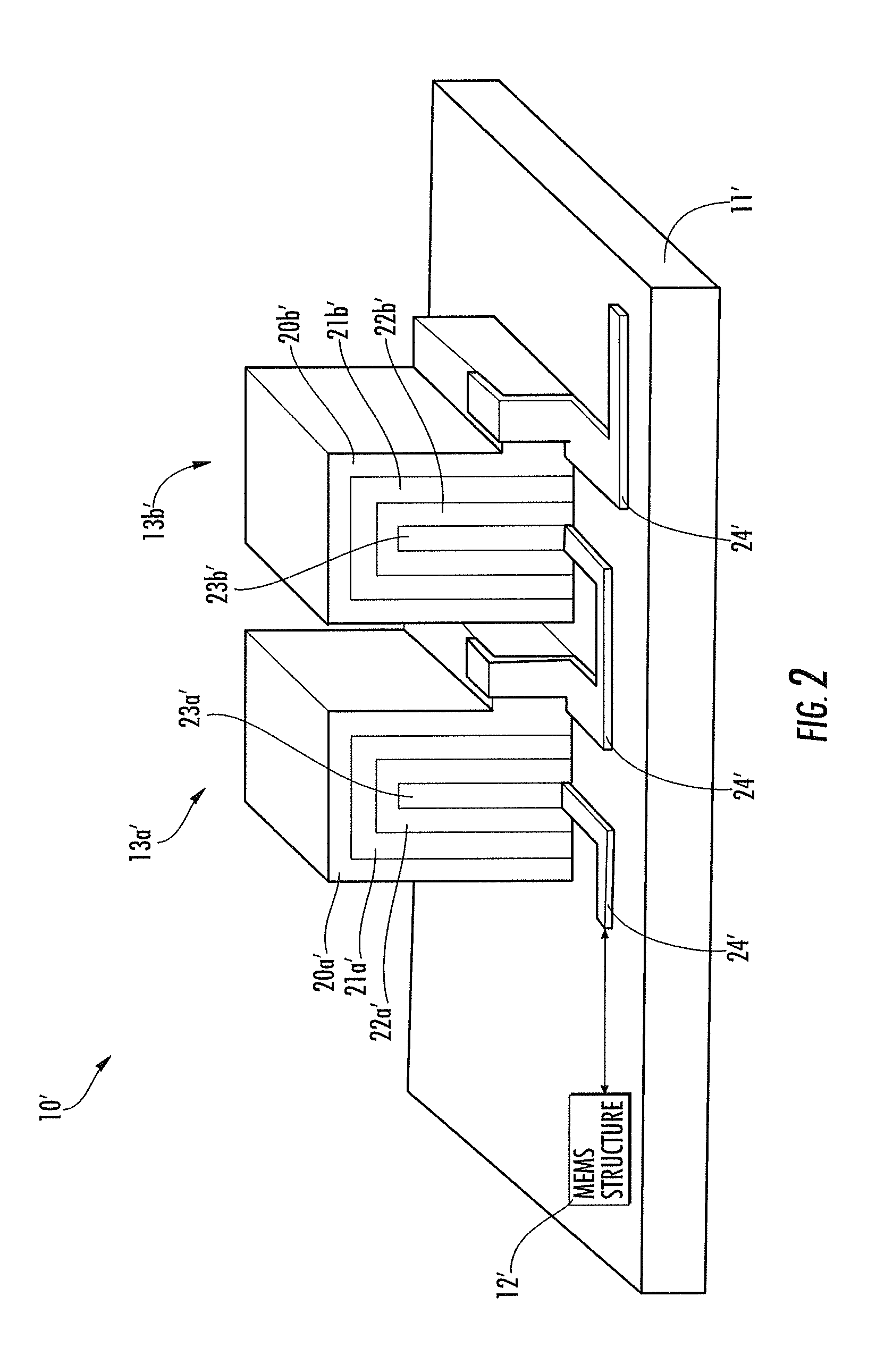
[0018]The present invention will now be described more fully hereinafter with reference to the accompanying drawings, in which preferred embodiments of the invention are shown. This invention may, however, be embodied in many different forms and should not be construed as limited to the embodiments set forth herein. Rather, these embodiments are provided so that this disclosure will be thorough and complete, and will fully convey the scope of the invention to those skilled in the art. Like numbers refer to like elements throughout, and prime notation is used to show similar elements in other embodiments.

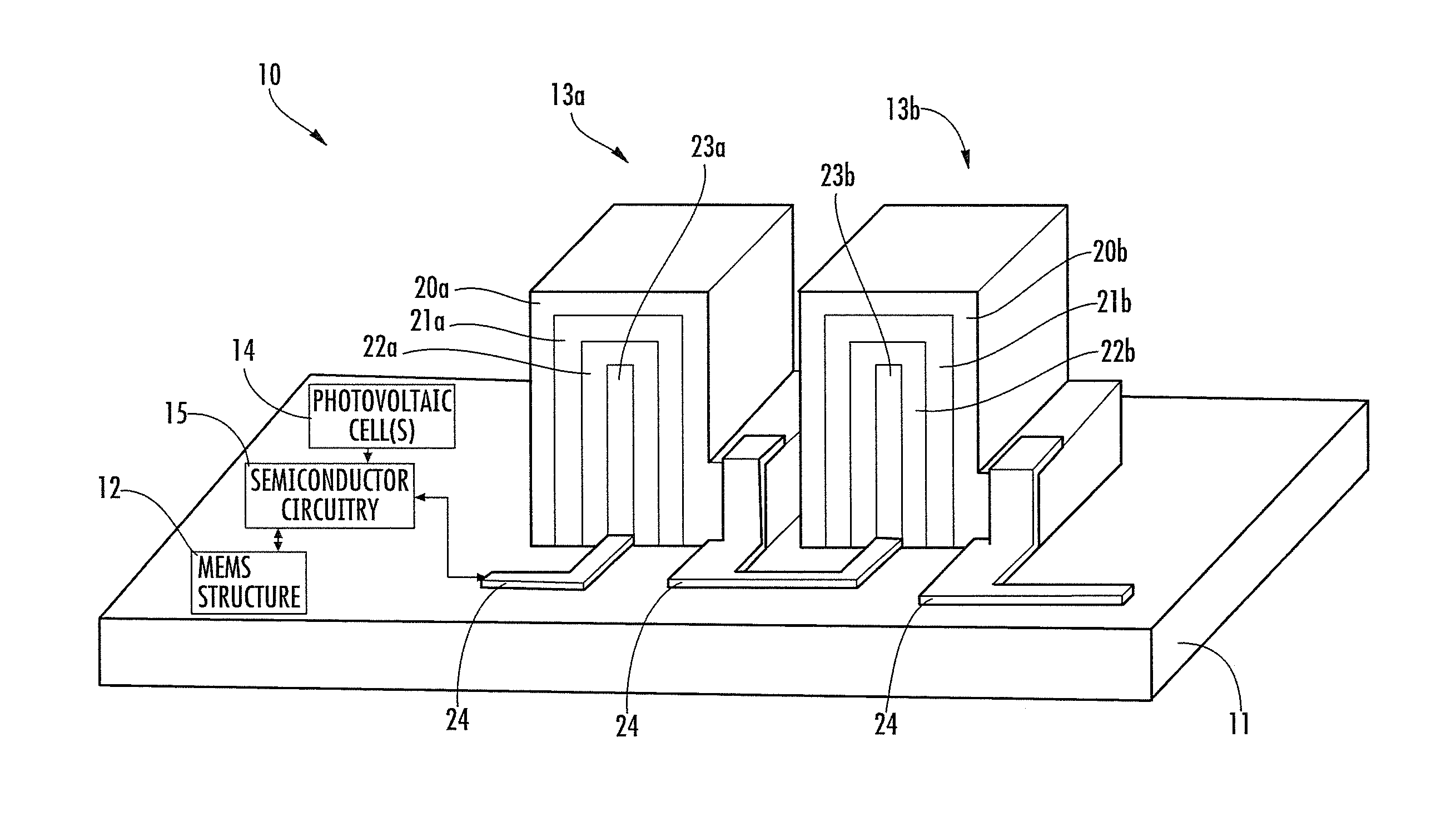
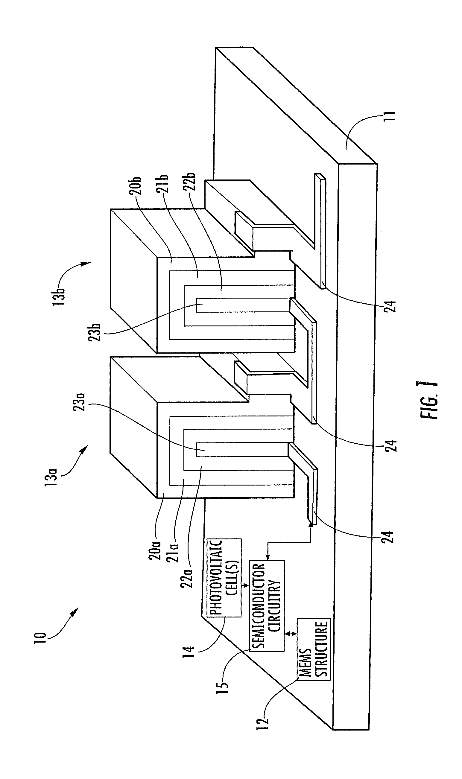
[0019]Referring initially to FIG. 1, a MEMS device 10 is now described. The MEMS device 10 includes a MEMS substrate 11 that carries two battery cells 13a, 13b, a MEMS structure 12, a photovoltaic cell 14, and semiconductor circuitry 15. The MEMS structure 12, the photovoltaic cell 14, and the semiconductor circuitry 15 are coupled to the battery cells 13a, 13b via conductive traces ...


PUM

PropertyMeasurementUnit
Heightaaaaaaaaaa
Heightaaaaaaaaaa
Temperatureaaaaaaaaaa

Abstract

A micro electrical-mechanical systems (MEMS) device INCLUDES a MEMS substrate and at least one MEMS structure on the MEMS substrate. In addition, there is at least one battery cell on the MEMS substrate coupled to the at least one MEMS structure. The at least one battery cell includes a support fin extending vertically upward from the MEMS substrate and a first electrode layer on the support fin. In addition, there is an electrolyte layer on the cathode layer, and a second electrode layer on the electrolyte layer. The support fin may have a height greater than a width. The first electrode layer may have a processing temperature associated therewith that exceeds a stability temperature associated with the second electrode layer.

Description

FIELD OF THE INVENTION[0001]The present invention relates to the field of micro electrical-mechanical systems (MEMS) and, more particularly, to battery cells for MEMS and related methods.BACKGROUND OF THE INVENTION[0002]Micro electrical-mechanical systems (MEMS) are typically made from components of 1 to 100 micrometers in size, and MEMS devices generally range in size from 20 micrometers to a millimeter, involving the integration of both electrical and mechanical elements, sensors, actuators, and the like on a substrate utilizing micro-fabrication technology. MEMS devices are particularly useful because they may combine the computational ability of microelectronics with the perception capabilities of microsensors and the precise control capabilities of microactuators. Indeed, the fabrication and integration of these elements on a single substrate may allow the realization of complete systems on a single chip.[0003]MEMS technology has already become commonplace in today's world and ...

Claims


Application Information

Patent Timeline
IPC IPC(8): H02J7/00H01M4/525H01M6/14H01M4/04
CPCH01M4/525H01M4/5825H01M10/0436Y10T29/49108H01M10/0585H01M10/465Y02E60/122H01M10/0562Y02E60/10
Inventor SHACKLETTE, LAWRENCE WAYNERENDEK, JR., LOUIS JOSEPHSMITH, DAVID M.
Owner HARRIS CORP
Why Eureka
Try Eureka