MEMS based space safety infrared sensor apparatus and method for detecting a gas or vapor

a space safety and infrared sensor technology, applied in the field of intrusion detection systems, can solve the problems of insufficient illumination of protected space, sensor sensitization to intruders, etc., and achieve the effect of scanning the ir signatur

Active Publication Date: 2006-02-23
HONEYWELL INT INC
View PDF8 Cites 16 Cited by
  • Summary
  • Abstract
  • Description
  • Claims
  • Application Information

AI Technical Summary

Benefits of technology

[0005] To address the above and other issues, the present invention is directed to a space safety apparatus monitoring a volume of space encompassing a field of view, the space safety apparatus for detecting an intrusion within the volume of space, the apparatus comprising a micro-electro-mechanical system (MEMS) having mirror elements in a mirror array for reflecting infra-red (IR) energy beam collected from the FOV; and an IR energy detector for detecting the IR energy reflected by the ME

Problems solved by technology

The problem with this arrangement is that other sources of IR energy within a zone or zones can be detected as alarm signals as well.
This also des

Method used


Image

  • MEMS based space safety infrared sensor apparatus and method for detecting a gas or vapor
  • MEMS based space safety infrared sensor apparatus and method for detecting a gas or vapor
  • MEMS based space safety infrared sensor apparatus and method for detecting a gas or vapor

Examples


first embodiment

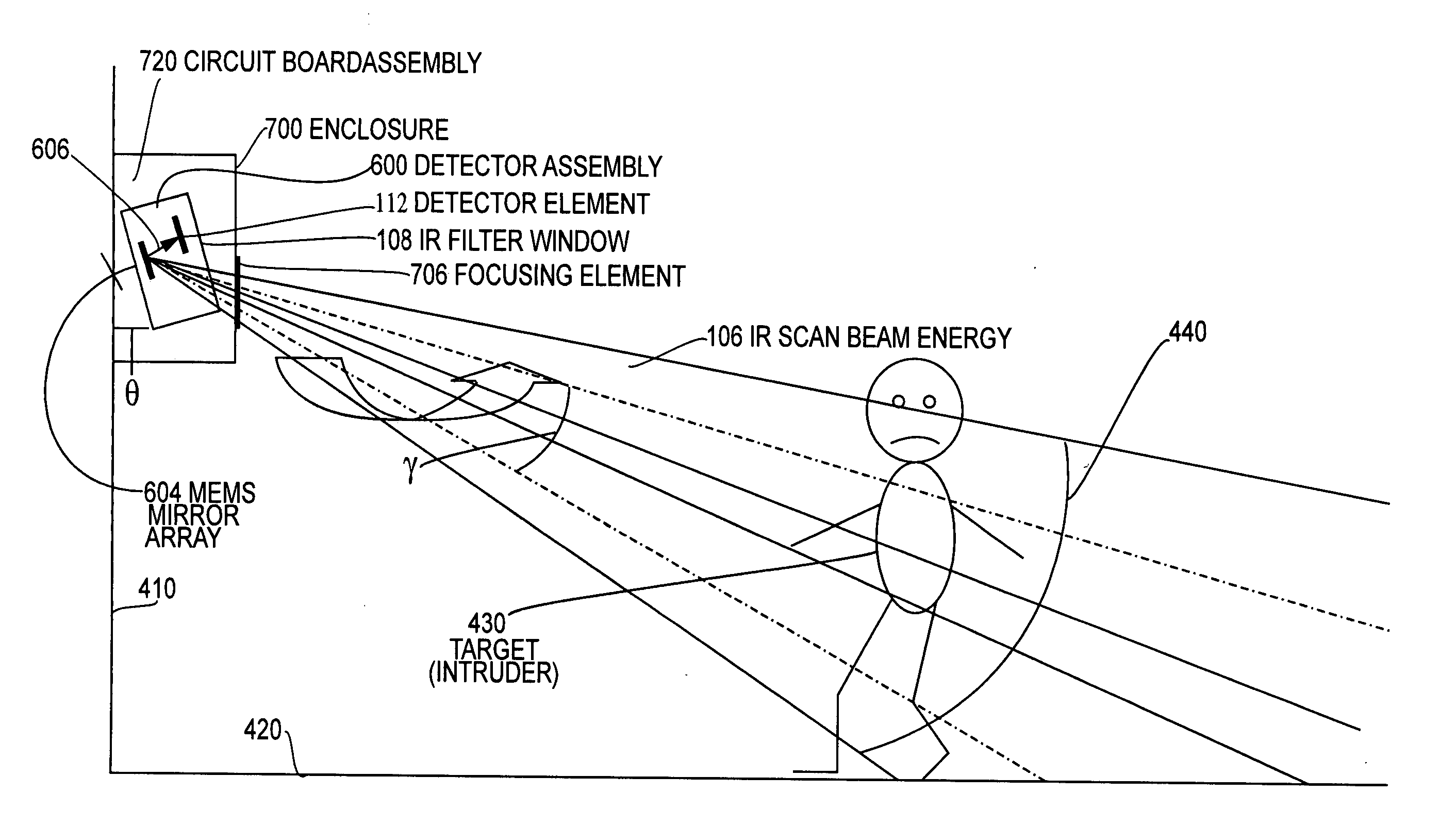
[0114]FIG. 13 is a method diagram of the steps of operating the MEMS based passive IR sensor detector assembly 600 of the present invention. In particular, step S1300 directs positioning the MEMS mirror 604 with respect to the active elements of the IR detector assembly 600. Step S1302 directs collecting the IR energy from the ith portion of the field of view (FOV) at a pre-determined scan rate. Step S1302 is achieved by performing either step S1302A or S1302B illustrated in FIGS. 13A and 13B, respectively. Step 1302A directs activating the MEMS mirror 604 of the present invention to traverse the FOV 440 of the IR detector assembly 600. Step 1302A is performed either by performing step S1302A1 or step S1302A2. Those skilled in the art recognize that step S1302 of collecting the IR energy inherently includes the steps of focusing the IR energy beam, filtering the IR energy beam, reflecting the IR energy beam by the MEMS mirror array onto a detector, detecting the IR energy beam by me...

second embodiment

[0117] In FIG. 13B, the alternative step S1302B of the present invention directs the signal controller 1116 to adjust the MEMS mirror 604 to switch to another focusing element 706 to traverse the FOV 440 of the IR detector assembly 600. Step S1302B is performed either by performing step S1302B1 or step S1302B2.

[0118] Step S1302B1 directs switching to another focusing element 706 during traversal of the FOV 440 in a non-chopping mode by either performing step 1302B1′ which directs traversing the IR zones 1150 of the FOV 440 in incremental, overlapping steps or by performing step S1302B1″ which directs traversing the IR zones 1150 of the FOV 440 in discrete, finite steps.

[0119] Alternatively, step S1302B2 directs switching to another focusing element 706 during traversal of the FOV 440 in a chopping mode by either performing step 1302B2′ which directs traversing the IR zones 1150 of the FOV 440 in incremental, overlapping steps or by performing step S1302B2″ which directs traversing ...

third embodiment

[0130]FIG. 15B is cross-sectional elevation view of a variation of the present invention wherein the wideband elements, i.e., wide IR band filter 108W; MEMS mirror 604W; IR detector 112W; amplifier 1102W; and A / D converter 1104W are each enclosed in or associated with a discrete wide band MEMS based IR detector 1400W while the narrow band elements, i.e., narrow IR band filter 108N; MEMS mirror 604N; IR detector 112N; amplifier 1102N are each enclosed in or associated with a discrete narrow band MEMS based IR detector 1400N. The two detectors 1400W and 1400N are separated by a distance d which is minimized to reduce the area which the collimated IR beam needs to be focused onto. An alternative approach is to make one detector housing which contains both the narrow IR band and wide IR band elements and separate them with a partition in the middle so as to minimize reflections and / or cross talk between the two detectors 1400W and 1400N.

[0131]FIG. 16 illustrates a plan view of a MEMS ba...


PUM


Abstract

A space safety apparatus monitoring a volume of space encompassing a field of view (FOV) for detecting an intrusion including a gas or vapor, and includes a micro-electro-mechanical system (MEMS) having mirror elements in a mirror array for reflecting infra-red (IR) energy beam collected from the FOV and an IR energy detector for detecting the IR energy reflected by the MEMS array and converting the IR energy to an output signal. A processor adjusts an angle of an element of the MEMS mirror array by varying a control signal, or by switching from one to another focusing element. The method includes detection in a volume of space by positioning a MEMS mirror array to reflect IR signal with respect to active elements of an IR detector; and collecting IR energy from an ith portion of the FOV.

Description

BACKGROUND OF THE INVENTION [0001] 1. Field of Invention [0002] The invention relates generally to the field of intrusion detection systems for animate, inanimate or gaseous substances relying on infrared signal detection and, more specifically, to a space safety infrared signal intrusion detection system which incorporates a micro-electro-mechanical system (MEMS) mirror array. [0003] 2. Description of Related Art [0004] Passive infrared (IR) sensors detect intruders moving within the field of view (FOV) by measuring the temperature gradient caused by an intruder. The sensor's FOV is fixed and is determined by the optical properties of the lens or mirror system. The FOV is subdivided into static active and inactive zones; the motion of an intruder from an active to an inactive zone is detected as an alarm. The IR energy from each active zone is focused on the IR detector and the IR detector cannot determine which active zone is collecting the energy. The problem with this arrangemen...

Claims


Application Information

Patent Timeline
IPC IPC(8): G08B13/18
CPCG08B13/193
Inventor ESKILDSEN, KENNETH G.LEE, ROBERT E.
Owner HONEYWELL INT INC
Why Eureka
Try Eureka