Steering device for vehicle

a steering device and vehicle technology, applied in the direction of magnetic circuit rotating parts, magnetic circuit shape/form/construction, transportation and packaging, etc., can solve the problems of uneven torque and deterioration of steering feeling in the automotive steering device of either of the aforesaid, so as to achieve further improvement of steering feeling, suppress loss of magnetic fluxes, and suppress uneven torque of electric motors.

Inactive Publication Date: 2007-05-17
JTEKT CORP
View PDF3 Cites 14 Cited by
  • Summary
  • Abstract
  • Description
  • Claims
  • Application Information

AI Technical Summary

Benefits of technology

[0012] According to this inventive aspect, the magnetic fluxes interlink with the coils in the predetermined directions, while changing the number of magnetic fluxes in the respective cores. Therefore, a loss of the magnetic fluxes can be suppressed as compared with the case where the direction of the interlinkage of the magnetic fluxes with the coils is changed. As a result, the unevenness of the torque of the electric motor can be suppressed. Therefore, unnatural fluctuation of the steering assist force applied from the electric motor is suppressed so that the steering feeling can be further improved.

Problems solved by technology

As a result, the direction of the magnetic fluxes 96 is changed with respect to the coils 95, resulting in unevenness of the torque.
This brings about a problem such that a steering feeling is deteriorated in the automotive steering device of either of the aforesaid types.

Method used


Image

  • Steering device for vehicle
  • Steering device for vehicle
  • Steering device for vehicle

Examples


Embodiment Construction

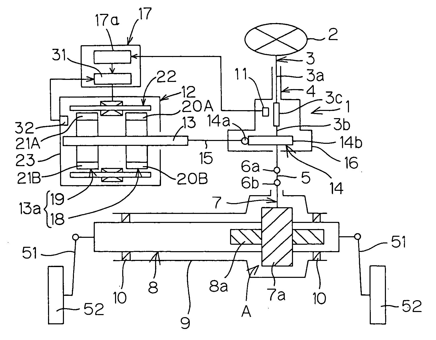
[0021] An automotive steering device according to one embodiment of the present invention will hereinafter be described with reference to the attached drawings. FIG. 1 is a schematic diagram illustrating the schematic construction of this automotive steering device.

[0022] The automotive steering device 1 includes a steering shaft 3 coupled to a steering member 2 such as a steering wheel, and a steering column 4 rotatably supporting the steering shaft 3 therein.

[0023] The automotive steering device 1 includes an intermediate shaft 5 coupled to the steering shaft 3 via a universal joint 6a, a pinion shaft 7 coupled to the intermediate shaft 5 via a universal joint 6b, and a rack shaft 8 as a steerable shaft extending transversely of a motor vehicle and having rack teeth 8a meshed with pinion teeth 7a provided around the pinion shaft 7. A steering mechanism A of a rack-and-pinion mechanism is constituted by the pinion shaft 7 and the rack shaft 8.

[0024] The steering shaft 3 is divid...


PUM


Abstract

An automotive steering device (1) includes an electric motor (12) which generates a steering assist force. The electric motor (12) includes a stator (22) surrounding a rotation shaft (13), and first and second rotors (18, 19) rotatable together with the rotation shaft (13). The stator (22) includes a plurality of cores (25A-25D) elongated parallel to an axis of the rotation shaft (13). An electric current is caused to flow through coils (26A-26D) wound around the respective cores (25A-25D), whereby the cores (25A-25D) are each formed with first and second magnetic poles (27A-27D, 28A-28D) having opposite polarities. The first and second magnetic poles (27A-27D, 28A-28D) are disposed longitudinally (L) opposite to each other with respect to the corresponding cores (25A-25D). As the rotation shaft (13) is rotated, a third magnetic pole (20n) of the first rotor (18) and a fourth magnetic pole (21s) of the second rotor (19) are respectively brought into opposed relation to the first and second magnetic poles (27A-27D, 28A-28D) of the cores (25A-25D) in the same phase. Magnetic fluxes (J) interlink with the coils (26A-26D) around the cores (25A-25D) in predetermined directions longitudinally (L) of the cores (25A-25D).

Description

TECHNICAL FIELD [0001] The present invention relates to an automotive steering device for an automobile or the like. BACKGROUND ART [0002] Automotive steering devices are broadly classified into a link type in which a steering member such as a steering wheel is mechanically coupled to a steering mechanism via a transmission member such as a steering shaft or the like and a steer-by-wire type in which the steering member is not mechanically coupled to the steering mechanism. [0003] Automotive steering devices of the former link type include an electric power steering device including an electric motor which generates a steering assist force according to operation of the steering member. A DC motor is typically used as the electric motor for the electric power steering device (see, for example, Japanese Unexamined Patent Publication No. 7-137644 laid open on May 30, 1995 and Japanese Unexamined Patent Publication No. 2002-153019 laid open on May 24, 2002). [0004] Automotive steering d...

Claims


Application Information

Patent Timeline
Patent Type & Authority Applications(United States)
IPC IPC(8): B62D5/04B62D6/00H02K1/27H02K16/02H02K21/14H02K21/24H02K29/06
CPCH02K21/14H02K21/24
Inventor UENO, HIROSHI
Owner JTEKT CORP
Why Eureka
Try Eureka