Light source apparatus

a technology for light source equipment and backlight apparatus, which is applied in the direction of lighting equipment, light sources, instruments, etc., can solve the problems of increasing and it is difficult to reduce the thickness of the backlight apparatus (light source equipment), so as to reduce the thickness of the backlight apparatus and increase the component cost and manufacturing cost.

Inactive Publication Date: 2013-03-21
CANON KK
View PDF3 Cites 16 Cited by
  • Summary
  • Abstract
  • Description
  • Claims
  • Application Information

AI Technical Summary

Benefits of technology

[0008]However, when a wire harness is used to connect a small light emitting substrate to an LED control substrate, as in the related art described above, increases in component cost and manufacturing cost occur. Further, when a wire harness is used, it becomes difficult to reduce a thickness of the backlight apparatus (light source apparatus).
[0009]The present invention provides a light source apparatus which can suppress brightness unevenness and color unevenness in a light emitting surface and which can be reduced in thickness without incurring a cost increase.
[0019]According to the present invention, brightness unevenness and color unevenness in a light emitting surface can be suppressed and a reduction in thickness can be achieved without incurring a cost increase.

Problems solved by technology

However, when a wire harness is used to connect a small light emitting substrate to an LED control substrate, as in the related art described above, increases in component cost and manufacturing cost occur.
Further, when a wire harness is used, it becomes difficult to reduce a thickness of the backlight apparatus (light source apparatus).

Method used


Image

  • Light source apparatus
  • Light source apparatus
  • Light source apparatus

Examples


first embodiment

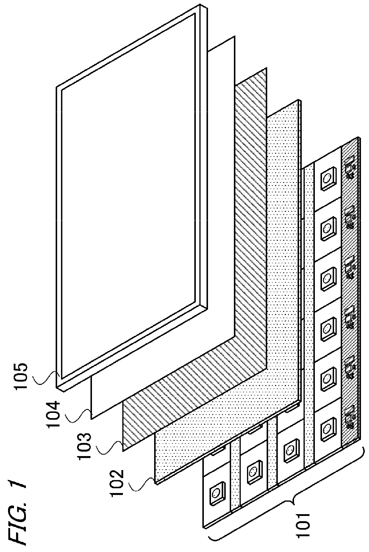
[0042]FIG. 1 is a pattern diagram showing an example of a configuration of a color image display apparatus to which the present invention can be applied. The color image display apparatus includes an LED backlight apparatus 101, a diffuser plate 102, a condensing sheet 103, a reflection type polarization film 104, and a color liquid crystal panel 105.

[0043]The LED backlight apparatus 101 is a light source apparatus (a backlight apparatus) that emits light (white light) onto aback surface of the color liquid crystal panel 105. The LED backlight apparatus 101 includes a plurality of LEDs serving as point light sources.

[0044]The diffuser plate 102 causes the LED backlight apparatus 101 to function as a surface light source by diffusing light from the plurality of LEDs.

[0045]The condensing sheet 103 improves a brightness (an on-screen brightness; a front brightness) of an image displayed on the color liquid crystal panel 105 by condensing the white light that is diffused by the diffuser...

second embodiment

[0112]In this embodiment, a light source apparatus including a brightness sensor that measures the light emitting brightness of the light source apparatus to suppress brightness unevenness and color unevenness caused by temporal deterioration and temperature variation in the respective light sources (LEDs) will be described. Alight source apparatus according to a second embodiment of the present invention will be described below. Note that in the drawings, identical reference numerals have been allocated to members that are identical to the first embodiment, and description thereof has been omitted.

[0113]FIG. 13 is a pattern diagram showing an example of a configuration of an LED backlight apparatus 701 according to the second embodiment of the present invention.

[0114]The LED backlight apparatus 701 according to this embodiment includes, similarly to the first embodiment, a plurality of (twenty-four) small light emitting substrates 702, intermediate substrates 704 to 706, and a cont...

third embodiment

[0139]In this embodiment, a configuration of a light source apparatus capable of reducing noise received by the measurement result of the brightness sensor (a brightness sensor signal) from the control signal will be described. Note that in the drawings, identical reference numerals have been allocated to members that are identical to the first and second embodiments, and description thereof has been omitted.

[0140]FIG. 17 is a pattern diagram showing an example of a configuration of an LED backlight apparatus 901 according to this embodiment.

[0141]The LED backlight apparatus 901 according to this embodiment includes the plurality of (twenty-four) small light emitting substrates 202, intermediate substrates 904 to 906, the control substrate 206, the brightness sensor 703, and an AD converter substrate 908.

[0142]The small light emitting substrate group 211 forming the first row and the small light emitting substrate group 212 forming the second row are connected by the intermediate su...


PUM


Abstract

A light source apparatus according to the present invention includes: a plurality of light emitting substrates arranged in matrix form, each having at least one light source; an intermediate substrate provided between respective rows of the plurality of light emitting substrates; and a driving unit that outputs a drive signal for driving the light sources, wherein a first supply wiring for supplying the drive signal to the light source provided on each of the plurality of light emitting substrates is printed on each of the light emitting substrates, and a first connection wiring for electrically connecting the first supply wirings printed on two light emitting substrates sandwiching the intermediate substrate is printed on the intermediate substrate.

Description

BACKGROUND OF THE INVENTION[0001]1. Field of the Invention[0002]The present invention relates to a light source apparatus.[0003]2. Description of the Related Art[0004]A color image display apparatus typically includes a color liquid crystal panel having color filters and a backlight apparatus that emits white light onto a back surface of the color liquid crystal panel. A fluorescent lamp such as a cold cathode fluorescent lamp (CCFL) is mainly used as a light source of the backlight apparatus. In recent years, however, light emitting diodes (LEDs), which are superior in terms of power consumption, lifespan, color reproducibility, and environmental load, have come into use as the light source of the backlight apparatus.[0005]A backlight apparatus (an LED backlight apparatus) that uses LEDs as a light source includes a large number of LEDs provided on a plate-shaped substrate, and is therefore capable of irradiating the color liquid crystal panel as a surface light source. However, a ...

Claims


Application Information

Patent Timeline
Patent Type & Authority Applications(United States)
IPC IPC(8): H05B37/02
CPCG02F2001/133612H05B37/02G09G3/3426G02F1/133603G02F1/133612H05B47/10
Inventor KURITA, MASANAO
Owner CANON KK
Why Eureka
Try Eureka