System and method for detecting leaks in sealed compartments

a leak detection and sealed compartment technology, applied in vehicle testing, structural/machine measurement, instruments, etc., can solve the problems of significant water intrusion, high visual inspection reliability, and significant expenditure of time and material for repairs

Inactive Publication Date: 2007-05-17
QST HLDG L L C
View PDF11 Cites 26 Cited by
  • Summary
  • Abstract
  • Description
  • Claims
  • Application Information

AI Technical Summary

Problems solved by technology

Since visual inspection can be highly unreliable, certain vehicle manufacturers utilize spray booths for subjecting fully assembled vehicles to an intense water spray to ensure that vehicles shipped from the factory will not leak due to faulty or damaged seals.
While this type of testing can be fairly reliable, it requires a worker to check for the presence of water in the cabin, and it is destructive in the sense that it can cause significant water intrusion in poorly sealed vehicles, or in vehicles where a window or door has been inadvertently left partially open, requiring significant expenditure of time and material for repairs due to water damage.
Additionally, the spray booths are expensive to install and maintain, and cannot be easily duplicated at vehicle service and repair facilities.
Ultrasonic energy may escape from the vehicle through a leak causing an increased amount of ultrasonic energy external to the vehicle at or close to the location of the leak.
Unfortunately, manufacturing an efficient and reliable leak detection system that utilizes non-destructive ultrasonic sensing capabilities can be difficult and expensive.
Such an environment can be extremely noisy and, therefore, adversely affect the performance of the leak detection system.

Method used


Image

  • System and method for detecting leaks in sealed compartments
  • System and method for detecting leaks in sealed compartments
  • System and method for detecting leaks in sealed compartments

Examples


Embodiment Construction

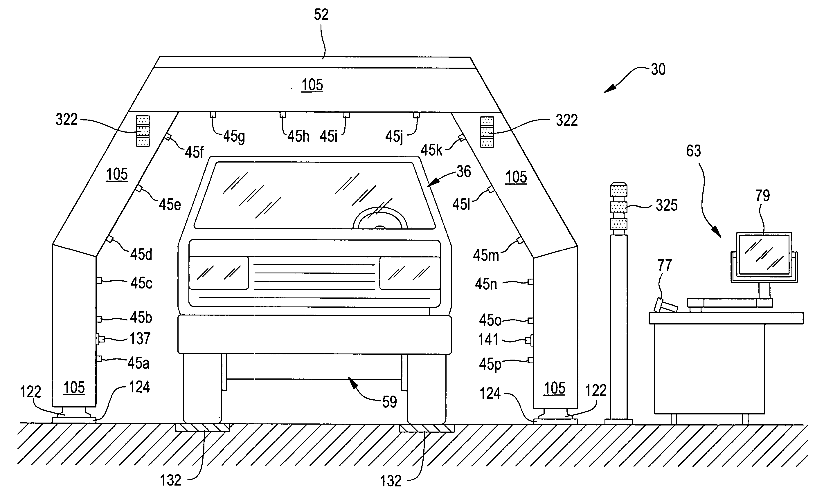
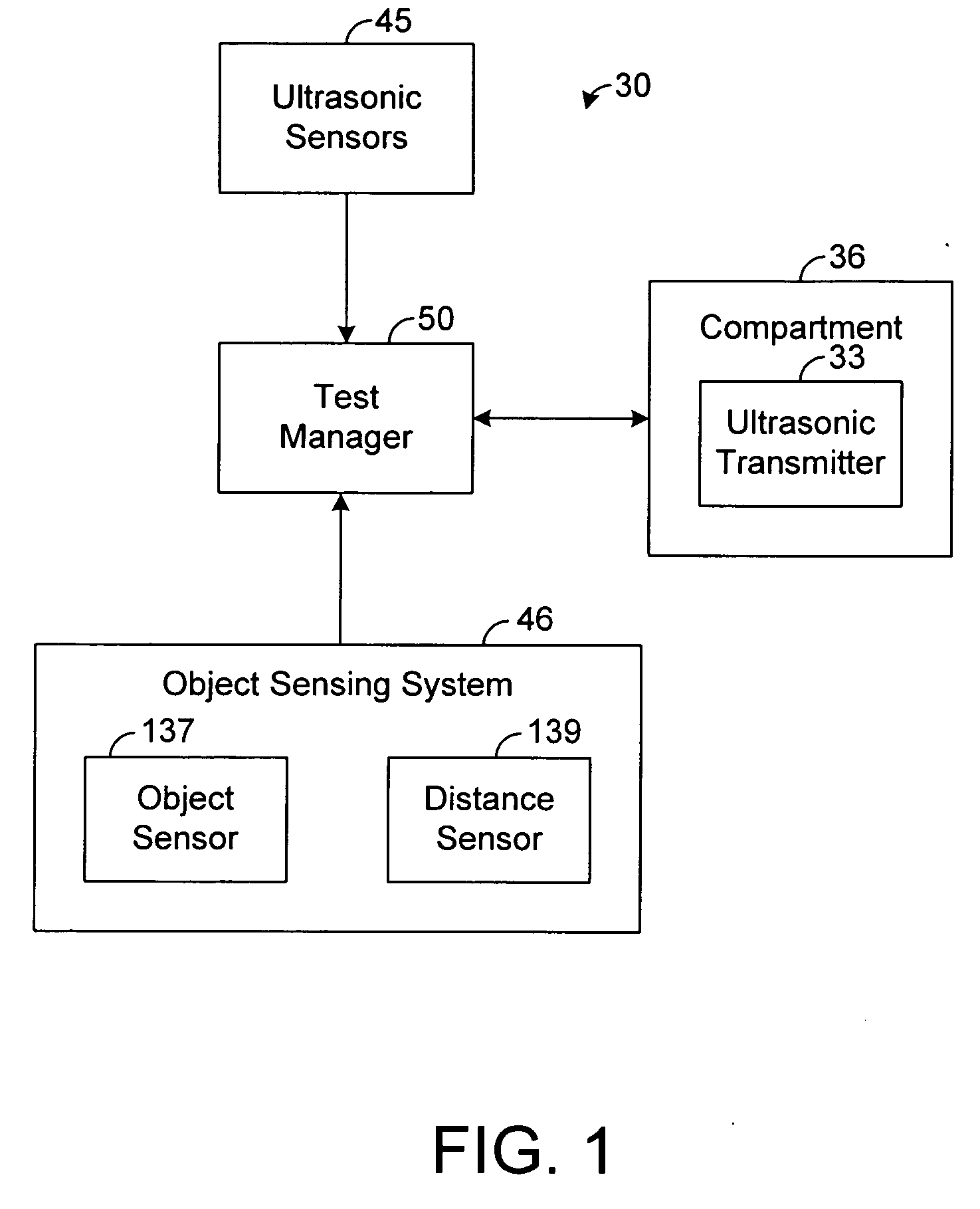
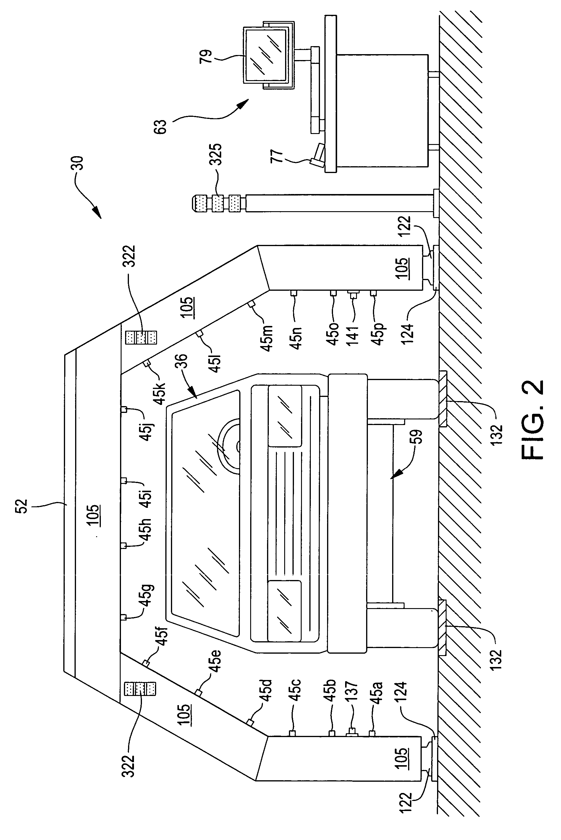
[0055] The present disclosure generally pertains to systems and methods for reliably detecting leaks in sealed compartments, such as compartments within vehicles. In several embodiments of the present disclosure, an apparatus having a sealed compartment, such as a vehicle (e.g., automobile, airplane, etc.), is moved past an array of ultrasonic sensors. An ultrasonic transmitter is placed in the sealed compartment and emits ultrasonic energy as the apparatus is moved past the ultrasonic sensors. A leak can be automatically and non-destructively detected by analyzing data from the ultrasonic sensors.

[0056] For purposes of illustration, the systems and methods of the present disclosure will be described hereafter as detecting leaks within sealed compartments, such as passenger compartments or trunks, of vehicles (e.g., automobiles, aircraft, boats, etc.). It is to be understood, however, that the systems and methods of the present disclosure may be similarly used to detect leaks in ot...


PUM


Abstract

A system for detecting leaks in sealed compartments, such as vehicles, comprises a transmitter, at least one sensor, and logic. In one embodiment, the transmitter is disposed within a vehicle and has a wireless communication interface and a transducer. The transducer is configured to transmit energy within a specified frequency range. The sensor is disposed outside of the vehicle and is configured to sense energy transmitted by the transducer. The sensor is further configured to provide a plurality of sample values, and each of the sample values is indicative of a respective amount of energy sensed by the sensor within the specified frequency range. The logic is configured to detect at least one leak in the vehicle based on the sample values and to provide an output indicative of the detected leak. The logic is configured to transmit, to the wireless communication interface, a wireless signal for controlling the transmitter.

Description

CROSS REFERENCE TO RELATED APPLICATIONS [0001] This application claims priority to U.S. Provisional Application No. 60 / 834,019, entitled “System and Method for Detecting Leaks in Sealed Compartments,” and filed on Jul. 28, 2006, which is incorporated herein by reference. This application also claims priority to U.S. Provisional Application No. 60 / 730,227, entitled “System and Method for Detecting Leaks in Sealed Compartments,” and filed on Oct. 25, 2005, which is incorporated herein by reference.RELATED ART [0002] In the manufacture or repair of products that include a sealed compartment, various methods have been used to determine how well the compartment is sealed, and where water or air intrusion (or extrusion) might occur. In the case of vehicles, for example, it is important to verify that water will not leak into the passenger compartment. Since visual inspection can be highly unreliable, certain vehicle manufacturers utilize spray booths for subjecting fully assembled vehicle...

Claims


Application Information

Patent Timeline
Patent Type & Authority Applications(United States)
IPC IPC(8): G08B21/00
CPCG01M3/24G01M17/007
Inventor FARRELL, SCOTT
Owner QST HLDG L L C
Why Eureka
Try Eureka