High Q and low stress capacitor electrode array

Active Publication Date: 2007-05-17
NXP USA INC
View PDF5 Cites 31 Cited by
  • Summary
  • Abstract
  • Description
  • Claims
  • Application Information

AI Technical Summary

Benefits of technology

[0006] An embodiment of the present invention provides a capacitor, comprising a solid electrode, an electrode broken into subsections with a signal bus lines connecting the subsections; and wherein the signal bus further connects the solid electrode with the electrode broken into subsections. The capacitor of an embodiment of the present invention may further comprise a voltage tunable dielectric material between the solid electrode and the electrode broken into subsections to enable the capacitor to be volt

Problems solved by technology

In past decades, all capacitor parameters were measured at a standard of

Method used


Image

  • High Q and low stress capacitor electrode array
  • High Q and low stress capacitor electrode array
  • High Q and low stress capacitor electrode array

Examples


Embodiment Construction

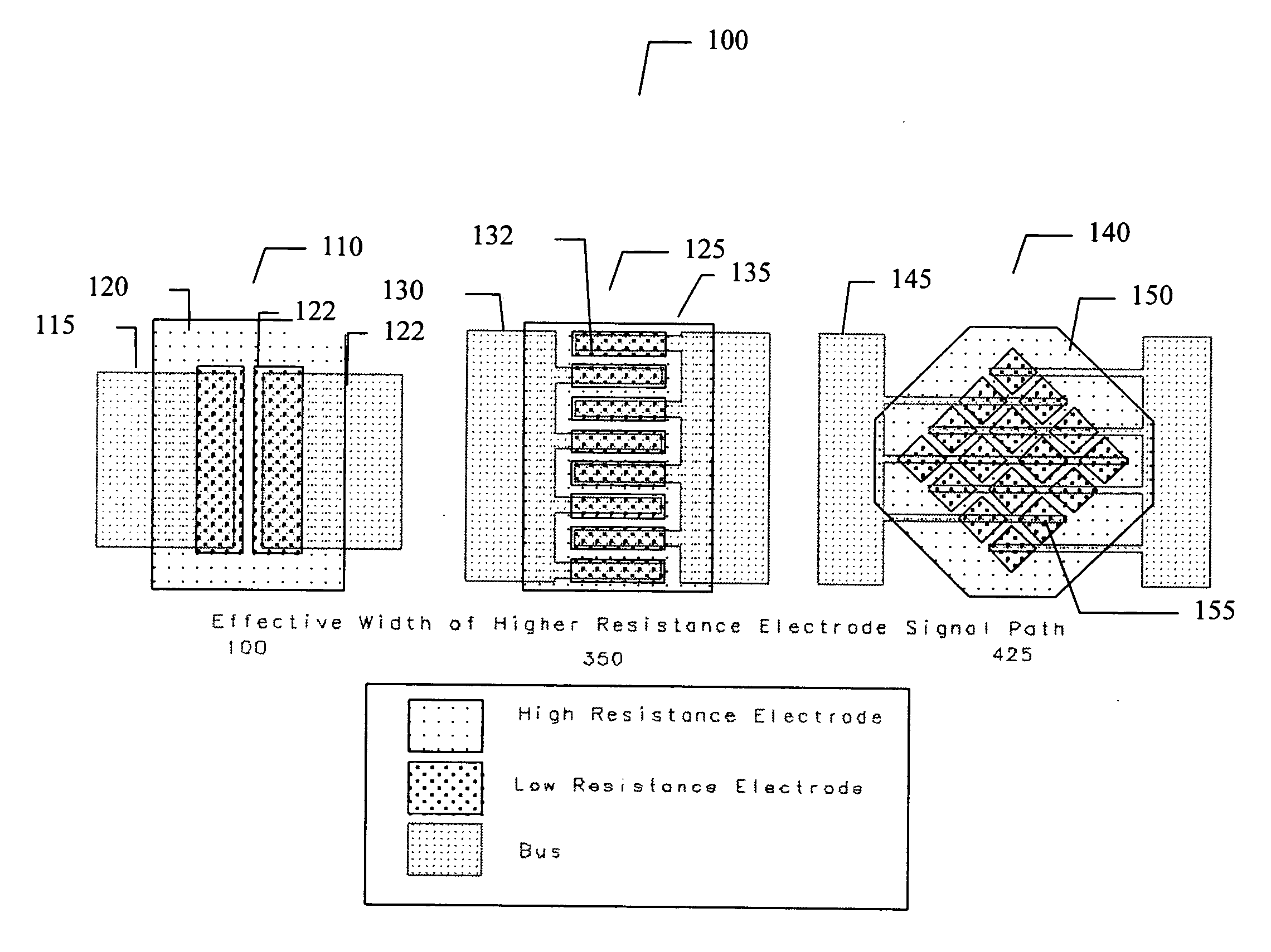
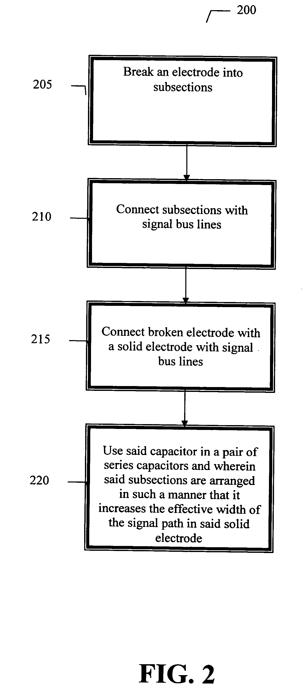
[0010] In the following detailed description, numerous specific details are set forth in order to provide a thorough understanding of the invention. However, it will be understood by those skilled in the art that the present invention may be practiced without these specific details. In other instances, well-known methods, procedures, components and circuits have not been described in detail so as not to obscure the present invention.

[0011] Use of the terms “coupled” and “connected”, along with their derivatives, may be used. It should be understood that these terms are not intended as synonyms for each other. Rather, in particular embodiments, “connected” may be used to indicate that two or more elements are in direct physical or electrical contact with each other. “Coupled” my be used to indicated that two or more elements are in either direct or indirect (with other intervening elements between them) physical or electrical contact with each other, and / or that the two or more elem...


PUM

PropertyMeasurementUnit
Shapeaaaaaaaaaa
Electric potential / voltageaaaaaaaaaa
Widthaaaaaaaaaa

Abstract

An embodiment of the present invention provides a capacitor, comprising a solid electrode, an electrode broken into subsections with a signal bus lines connecting the subsections; and wherein the signal bus further connects the solid electrode with the electrode broken into subsections.

Description

CROSS-REFERENCE TO RELATED APPLICATION [0001] This application claims the benefit of priority under 35 U.S.C Section 119 from U.S. Provisional Application Ser. No. 60 / 736,366, filed Nov. 14, 2005, entitled, HIGH Q AND LOW STRESS CAPACITOR ELECTRODE ARRAY, by James Martin. BACKGROUND OF THE INVENTION [0002] One of the most important parameters in evaluating a high frequency chip capacitor is the Q factor, or the related equivalent series resistance (ESR). In theory, a “perfect” capacitor would exhibit an ESR of 0 (zero) ohms and would be purely reactive with no real (resistive) component. The current going through the capacitor would lead the voltage across the capacitor by exactly 90 degrees at all frequencies. [0003] In real world usage, no capacitor is perfect, and will always exhibit some finite amount of ESR. The ESR varies with frequency for a given capacitor, and is “equivalent” because its source is from the characteristics of the conducting electrode structures and in the in...

Claims


Application Information

Patent Timeline
IPC IPC(8): H01G4/005
CPCH01G7/06H01G4/228Y10T29/43H01L28/87H01G4/38Y10T29/49005H01L23/5223Y10T29/435H01L2924/0002
Inventor MARTIN, JAMES
Owner NXP USA INC
Why Eureka
Try Eureka