Illuminated shelf

a shelf and light technology, applied in the field of shelves, can solve the problems of not considering the possibility of power surges, and reducing the life and effectiveness of illuminated shelves, so as to achieve the effect of easy assembly and disassembly, and minimal time, effort and cos

Inactive Publication Date: 2007-05-17
GEMTRON
View PDF4 Cites 46 Cited by
  • Summary
  • Abstract
  • Description
  • Claims
  • Application Information

AI Technical Summary

Benefits of technology

[0004] The present invention is directed to an illumination device and particularly an illuminated shelf which includes a transparent light transmitting tempered glass panel, opposite side housings, and each side housing being constructed from two housing parts which can be readily assembled and disassembled to access a compartment housing illumination devices, such as a light pipe, LED's, etc. The side housings each have a slot which receives an edge of the tempered glass panel and each housing further includes means for securing the shelf to an associated support, such as the interior of a refrigerator compartment. By providing a housing which can be readily opened and closed, any problems associated with lighting within each chamber defined by each housing can be analyzed, repaired, and the shelf replaced with a minimum of time, effort and cost.
[0005] Each side housing is preferably formed of two relatively long housing bodies with one housing body being provided with the slot to accommodate an edge portion of an associated tempered glass panel. The other housing body is preferably provided with integral fastening means for securing the same to an interior of a refrigerator compartment. Male and female snap-securing or coupling means are carried by the housing bodies to facilitate the rapid attachment and detachment thereof to each other.

Problems solved by technology

However, the latter expectation does not account for the possibility of power surges which could burn all the lights out, liquid leakage from products which would create a short to likewise create a short and prevent any illumination whatever, a broken wire between lights, etc.
As a matter of fact, front and rear edges of the tempered glass plate are turned up to form a spillage-containment volume with the associated end caps, but should sealant, bonding, encapsulation or the like include voids or fissures or deteriorate to provide such product, liquid spillage would readily enter the end caps causing a short and thereby reduce the life and effectiveness of the illuminated shelf.

Method used


Image

  • Illuminated shelf
  • Illuminated shelf
  • Illuminated shelf

Examples


Embodiment Construction

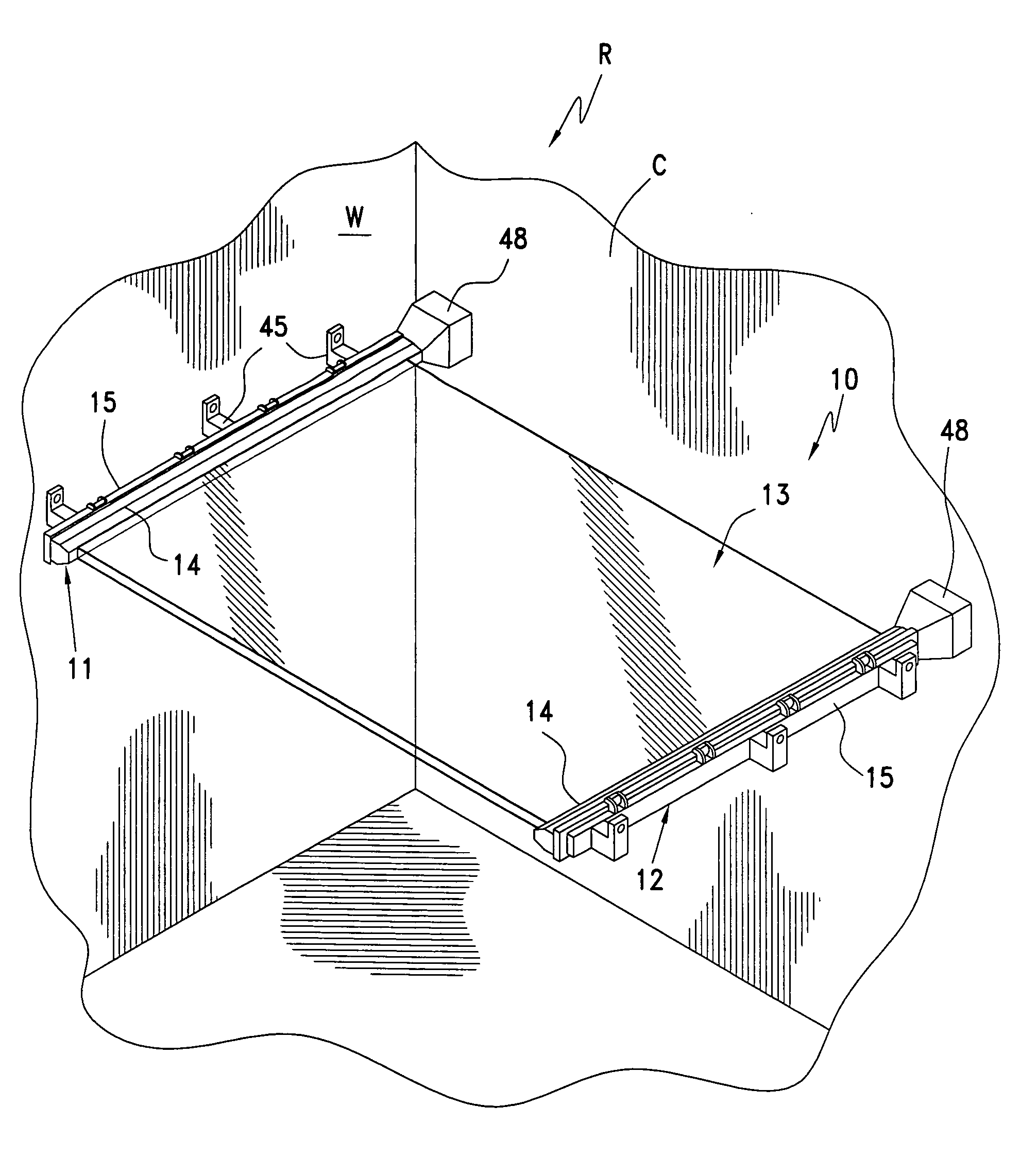
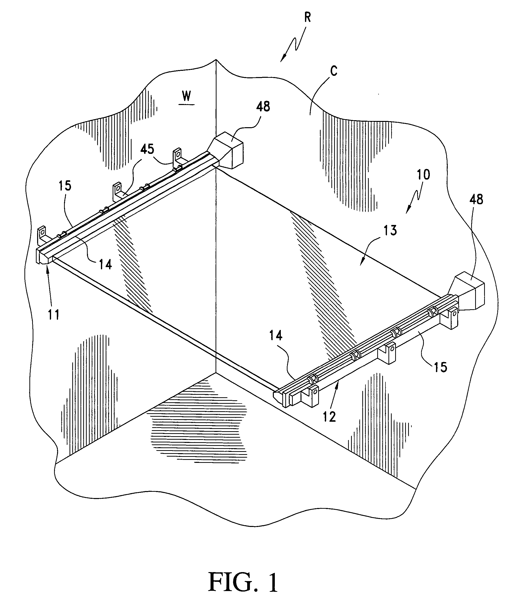
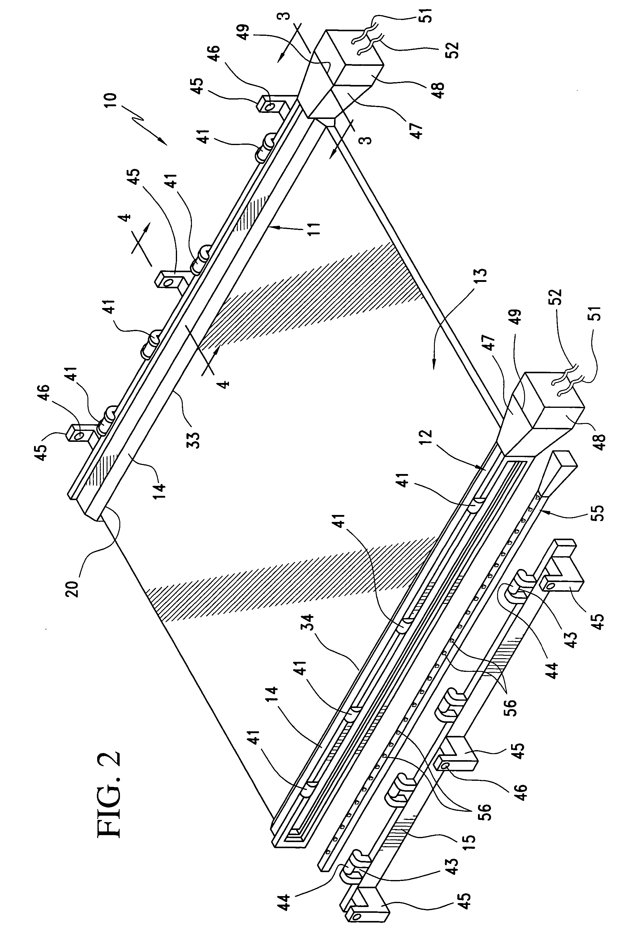
[0027] A novel illumination device constructed in accordance with this invention, which is preferably in the form of a shelf, is illustrated in FIGS. 1 through 3 of the drawings, and is generally designated by the reference numeral 10.

[0028] The shelf 10 is preferably associated with a compartment C of a refrigerator R, as is best illustrated in FIG. 1 of the drawings. However, the shelf 10 can easily be utilized in other structures, such as retail store display cases, furniture cabinetry (dish display cases), utility shelves for workshops, wash rooms, etc. No matter the particular utilization of the shelves of this invention, each of the various shelves disclosed herein is designed to be illuminated directly or indirectly to thereby better illuminate articles or products supported upon, above or below the shelves to aid consumer selection thereof.

[0029] The shelf 10 includes two substantially identical housings 11, 12 which house therebetween a plate, panel or member of light-tra...


PUM


Abstract

An illuminated shelf includes a tempered transparent glass panel having edges each housed in a slot of a housing defining a chamber through which and / or in which light is generated to illuminate the transparent panel. Each housing is preferably snap-secured together to access the chamber interior for purposes of replacement and / or repair. Each housing can be totally or partially encapsulated and the encapsulation includes conductors which are operative in any position of vertical adjustment or sliding adjustment of the shelf.

Description

CROSS-REFERENCE TO RELATED APPLICATIONS [0001] This Application is a divisional application of U.S. patent application Ser. No. 10 / 602,863 filed on Jun. 25, 2003 and now Pat. No.______BACKGROUND OF THE INVENTION [0002] The invention relates to shelving in general and specifically to an illuminated refrigerator shelf and a method of manufacture thereof. [0003] Patent Application Publication No. U.S. 2003 / 0038571 A1 which published on Feb. 27, 2003 in the name of Thomas W. Obrock et al. discloses the closest prior art known to the applicant which includes a refrigerator shelf having side edge lighting. The shelf of FIGS. 7 through 14 and particularly FIGS. 10 through 14 includes a flat plate of light transmitting material, such as tempered glass, having along each of side edges thereof an end cap with each end cap carrying a plurality of spaced lights or bulbs which are appropriately connected to a 12 volt electrical current source for edge-illuminating the glass plate. Each of the en...

Claims


Application Information

Patent Timeline
Patent Type & Authority Applications(United States)
IPC IPC(8): F25D27/00A47F5/00A47F11/10F21S2/00F21V8/00F21V33/00F21Y101/02F25D25/02
CPCA47B97/00A47F5/0043A47F11/10F21V33/0044F21W2131/305F25D25/02F25D27/00F25D2325/022F25D2400/40G02B6/0028G02B6/0086G02B6/0095
Inventor BIENICK, CRAIG
Owner GEMTRON
Why Eureka
Try Eureka