Thermal detonator with multiple light sources and reflective enclosure

a technology of reflective enclosure and detonator, which is applied in the field of air heaters, can solve the problems that the walls or other types of interior surfaces of the heaters themselves are not designed to raise the temperature to any significant amount, and achieve the effects of increasing the intensity of radiant energy, high reflective effect, and easy removal for maintenan

Inactive Publication Date: 2007-05-17
BERGSTEIN DAVID M
View PDF49 Cites 11 Cited by
  • Summary
  • Abstract
  • Description
  • Claims
  • Application Information

AI Technical Summary

Benefits of technology

[0005] Accordingly, it is an advantage of the present invention to provide an infrared light heating apparatus that uses multiple infrared light sources that are located within a chamber, which direct light toward a chamber wall (typically in the shape of a cylinder), in which the interior surface of this wall is highly reflective and increases the effect of the intensity of the radiant energy being emitted from the light sources, in which the chamber has an inlet and an outlet to allow air to pass therethrough, and the air will be heated by the radiant energy.
[0006] It is another advantage of the present invention to provide a chamber with multiple light sources that are directed toward an outer wall of the chamber which is highly reflective, in which there are multiple light sources that are positioned along an interior centerline rod that is easily removable for maintenance purposes, in which the highly reflective interior surface increases the thermal effect of the radiant energy that raises the temperature of air passing through the chamber.
[0007] It is yet another advantage of the present invention to provide an air heating apparatus that includes a chamber with an inlet and an outlet with air passing therethrough, in which the interior surface of the chamber is highly reflective, and in which there are multiple infrared light sources within the chamber that are directing radiant energy toward the highly reflective surfaces which tend to increase the thermal effect of the radiant energy, in heating the passing air.
[0008] It is still another advantage of the present invention to provide a detonator apparatus that comprises a chamber with at least one infrared light source within the chamber, in which the interior surfaces of the chamber are highly reflective and tend to increase the thermal effect of the radiant energy produced by the light source(s), in which the chamber walls are raised in temperature at a substantially uniform rate throughout all of the surface areas of the walls, and when reaching a predetermined temperature, will tend to ignite a layer of explosive material that is positioned around the chamber's interior walls, thereby creating a detonator with a very uniform ignition characteristic.
[0009] Additional advantages and other novel features of the invention will be set forth in part in the description that follows and in part will become apparent to those skilled in the art upon examination of the following or may be learned with the practice of the invention.
[0010] To achieve the foregoing and other advantages, and in accordance with one aspect of the present invention, an air-heating apparatus is provided, which comprises: an enclosure having an outer surface and an inner surface, the enclosure having an inlet air opening and an outlet air opening, the inner surface substantially forming a volume through which air passes as an air flow from the inlet air opening to the outlet air opening, the enclosure's inner surface being highly reflective; an elongated member that is positioned substantially within the volume; and a plurality of light sources mounted to the elongated member, the light sources being positioned so that they emit radiant energy substantially toward the inner surface of the enclosure; wherein: (a) the light sources are spaced-apart from one another along the surface of the elongated member; (b) a spacing between the light sources and the inner surface of the enclosure allows much of the radiant energy to be reflected by the inner surface in a direction that does not directly intersect the light sources; and (c) the air flow is heated by the radiant energy as the air passes through the volume.

Problems solved by technology

Some of these conventional “chamber” heaters are designed to heat objects or specimens that are placed within the heater, however, the walls or other types of interior surfaces of the heater are themselves not designed to be raised in temperature to any significant amount.

Method used


Image

  • Thermal detonator with multiple light sources and reflective enclosure
  • Thermal detonator with multiple light sources and reflective enclosure
  • Thermal detonator with multiple light sources and reflective enclosure

Examples


Embodiment Construction

[0024] Reference will now be made in detail to the present preferred embodiment of the invention, an example of which is illustrated in the accompanying drawings, wherein like numerals indicate the same elements throughout the views.

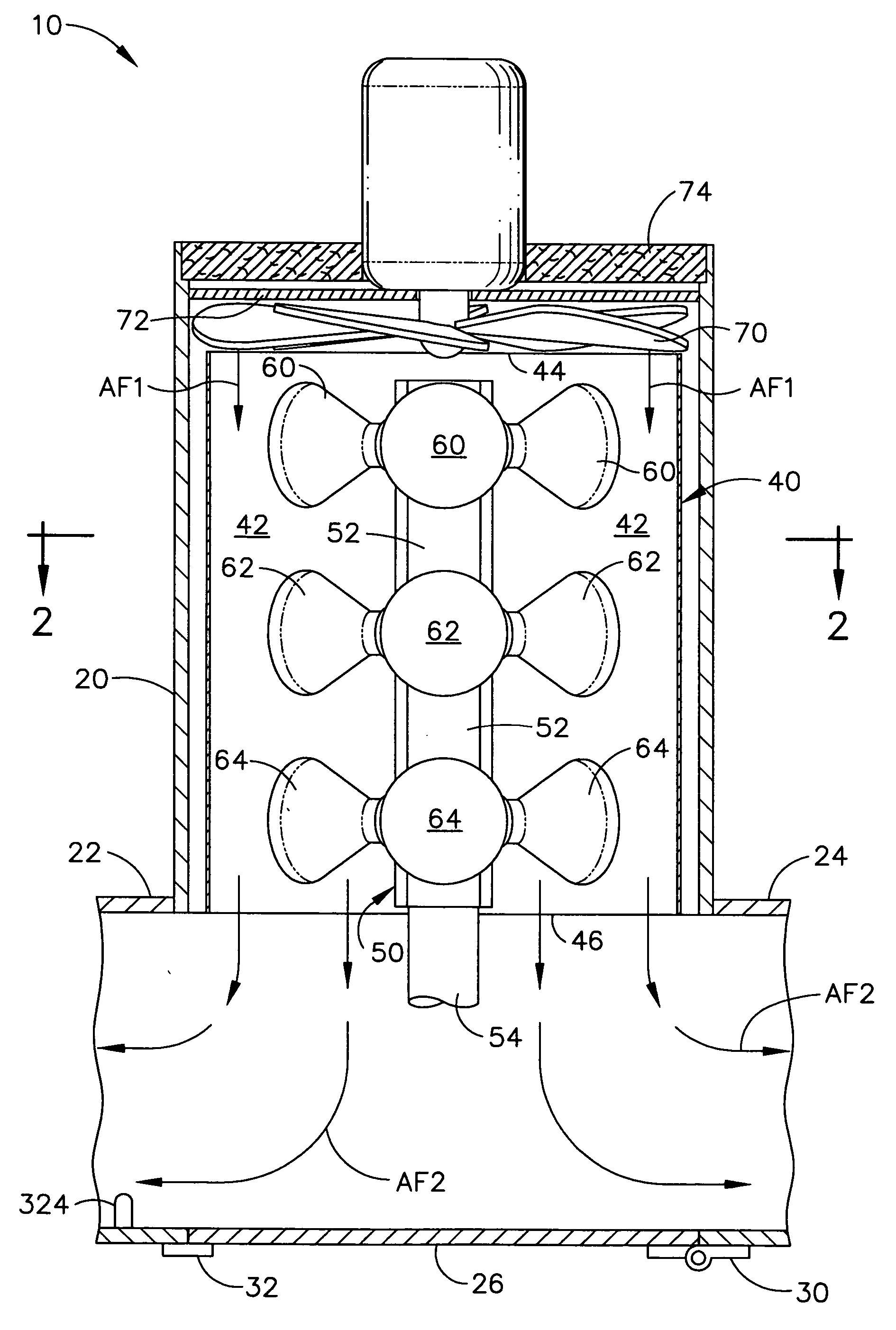
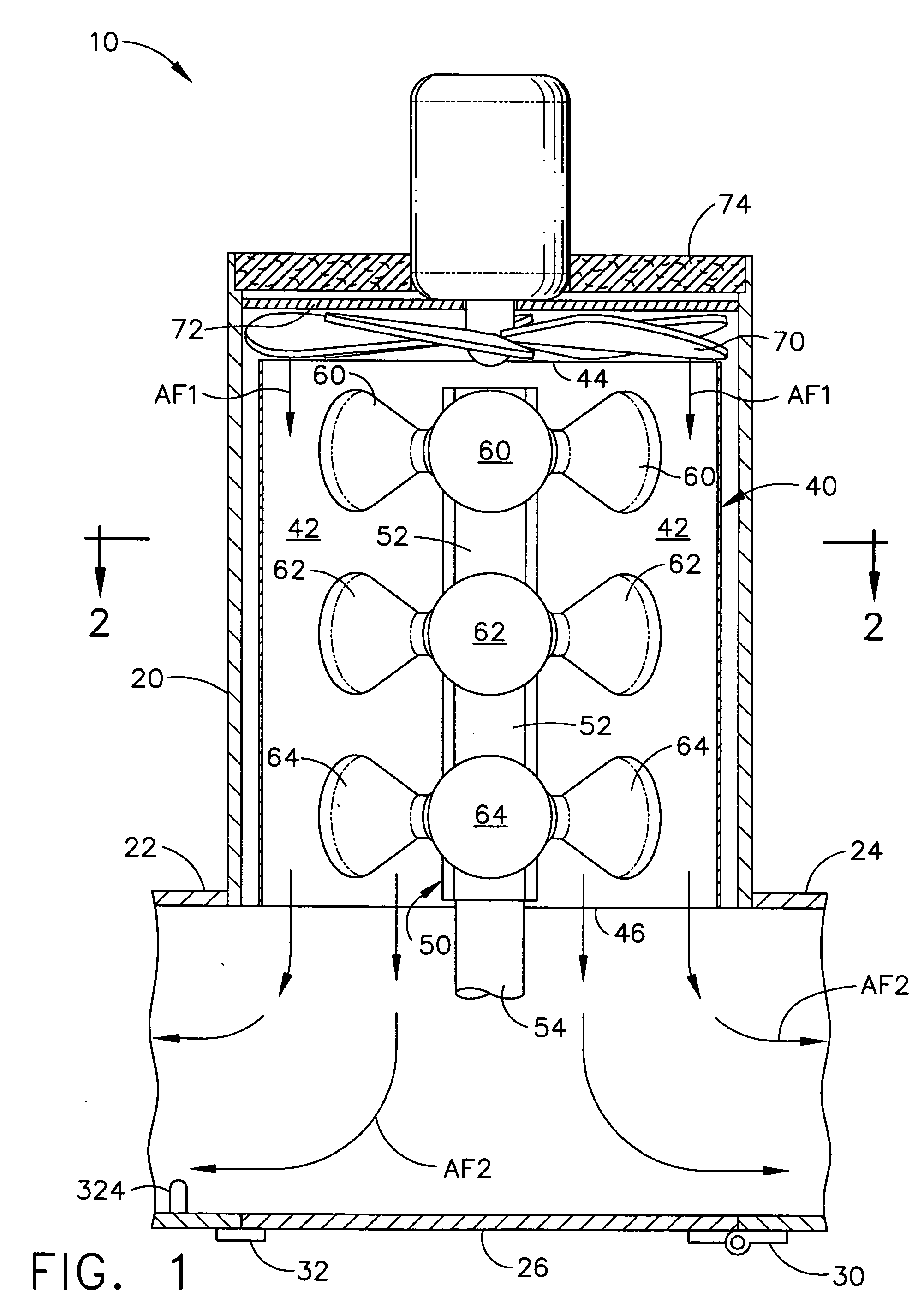
[0025] The present invention comprises an air-heating system that uses mirrored surfaces to “multiply” the effect of thermal energy that is generated by one or more infrared light-sources, or heat-sources. The mirrored surfaces reflect the infrared photons within a chamber or cavity, and essentially act as a photon “multiplier”. This increases the effective thermal output power of the infrared heat-sources by a considerable percentage. Additional increases in thermal energy are also created by convection and conduction of the chamber's interior metal structure.

[0026] Referring now to FIG. 1, a cylindrical chamber is illustrated, generally designated by the reference numeral 10. The overall shape of the cylindrical chamber is mainly determined by an out...


PUM


Abstract

An air heater is provided for use in buildings or other structures. The air heater uses infrared lamps to generate a temperature rise in a forced air chamber that contains several infrared lamps, in which two ends of the chamber act as an inlet and an outlet, and in which the chamber has a highly reflective interior surface that reflects the light being emitted by the lamps to multiply the thermal effect of the infrared light sources. An alternative embodiment uses a closed chamber, in which the temperature rise causes the unit to act as a detonator.

Description

CROSS-REFERENCE TO RELATED APPLICATIONS [0001] The present application is a divisional application of Ser. No. 11 / 254,494, titled “INFRARED AIR HEATER,” filed on Oct. 20, 2005.TECHNICAL FIELD [0002] The present invention relates generally to air heating equipment and is particularly directed to an air heater of the type which uses infrared lamps to generate a temperature rise in a forced air chamber. The invention is specifically disclosed as a chamber with several infrared lamps within the chamber, in which two ends of the chamber act as an inlet and an outlet, and in which the chamber has a highly reflective interior surface that reflects the light being emitted by the lamps to multiply the effect of the infrared light sources. An alternative embodiment uses a closed chamber, in which the temperature rise causes the unit to act as a detonator. BACKGROUND OF THE INVENTION [0003] Air heaters that use infrared lamps have been around for years, and are typically broken into two differ...

Claims


Application Information

Patent Timeline
Patent Type & Authority Applications(United States)
IPC IPC(8): A61H33/08
CPCF24H3/0405H05B3/008
Inventor BERGSTEIN, DAVID M.
Owner BERGSTEIN DAVID M
Why Eureka
Try Eureka