
Image forming apparatus

a technology of image forming apparatus and forming plate, which is applied in the direction of electrographic process apparatus, instruments, optics, etc., can solve the problems of increasing the time taken for this switchover as a loss time, and achieve the effect of reducing the loss time and reducing the print speed

Active Publication Date: 2007-05-17
KONICA MINOLTA BUSINESS TECH INC
View PDF3 Cites 10 Cited by
  • Summary
  • Abstract
  • Description
  • Claims
  • Application Information

AI Technical Summary

Benefits of technology

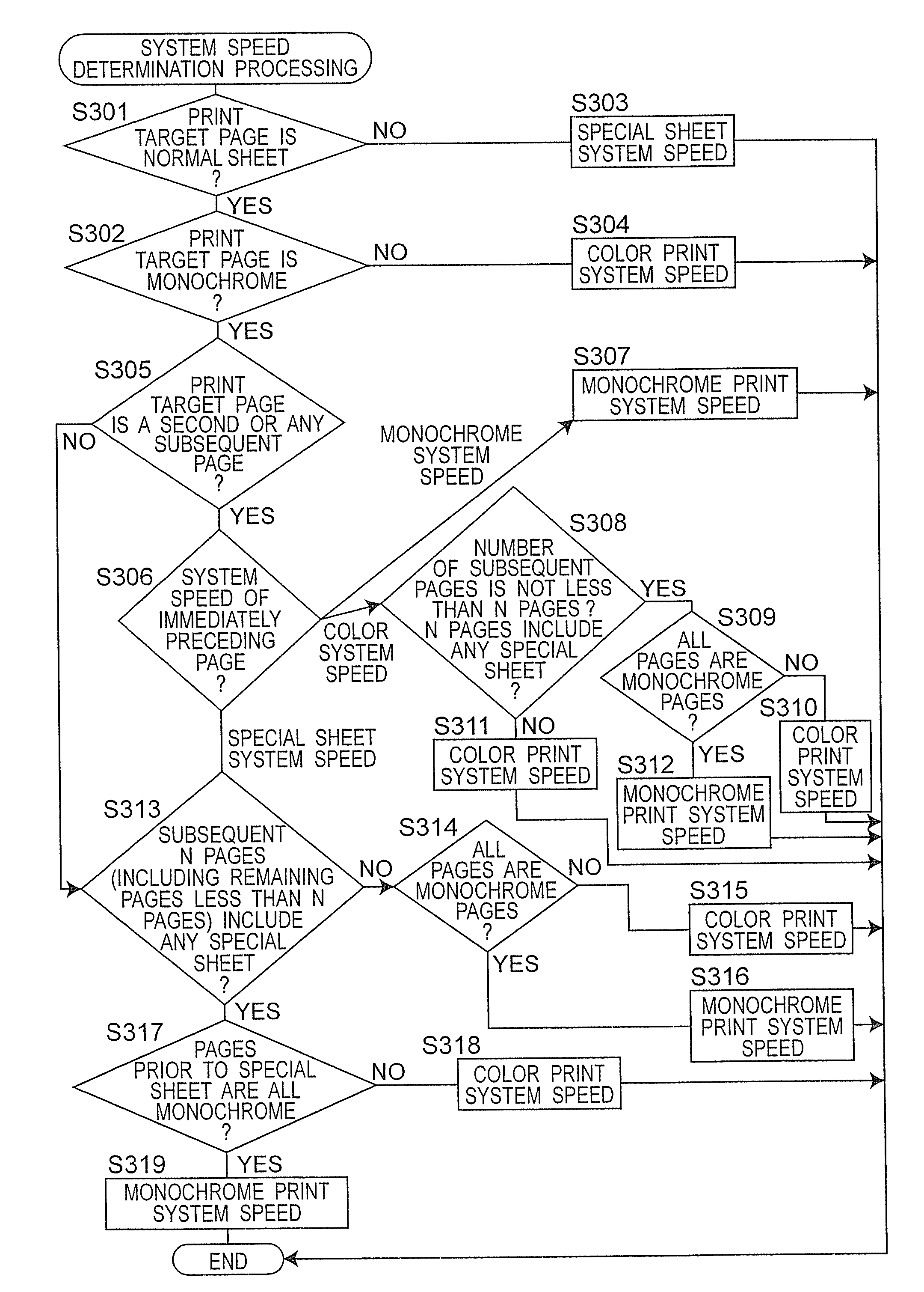
[0007] An object of the present invention is to provide an image forming apparatus, which can optimize switchover of a system speed at the time of monochrome printing by focusing attention on the fact that monochrome pages can be printed at the system speed of a color print mode, decrease loss time generated by change in system speed caused by switchover between monochrome and color print modes, and minimize decrease in printing number per time.
[0040] According to the image forming apparatus of the present invention, the system speed in the case where the print target page is monochrome is determined in consideration of the continuity of monochrome pages immediately before and after a print target page as well as the presence of special sheets, and this makes it possible to reduce a loss time caused by switchover of the system speeds. When a mixture ratio of monochrome and color pages in a print target document is high, influence of a decreased print speed during monochrome printing executed at the system speed for a color print mode in the image forming apparatus of the present invention is smaller than influence of a print stop time due to a loss time caused by system speed changes, and consequently a period of time till the end of printing of the print target document is rather shortened.

Problems solved by technology

However, depending of a mixture rate of color and monochrome pages, the print mode should be switched frequently and a time taken for this switchover increases as a loss time.

Method used


Image

  • Image forming apparatus
  • Image forming apparatus
  • Image forming apparatus

Examples


Embodiment Construction

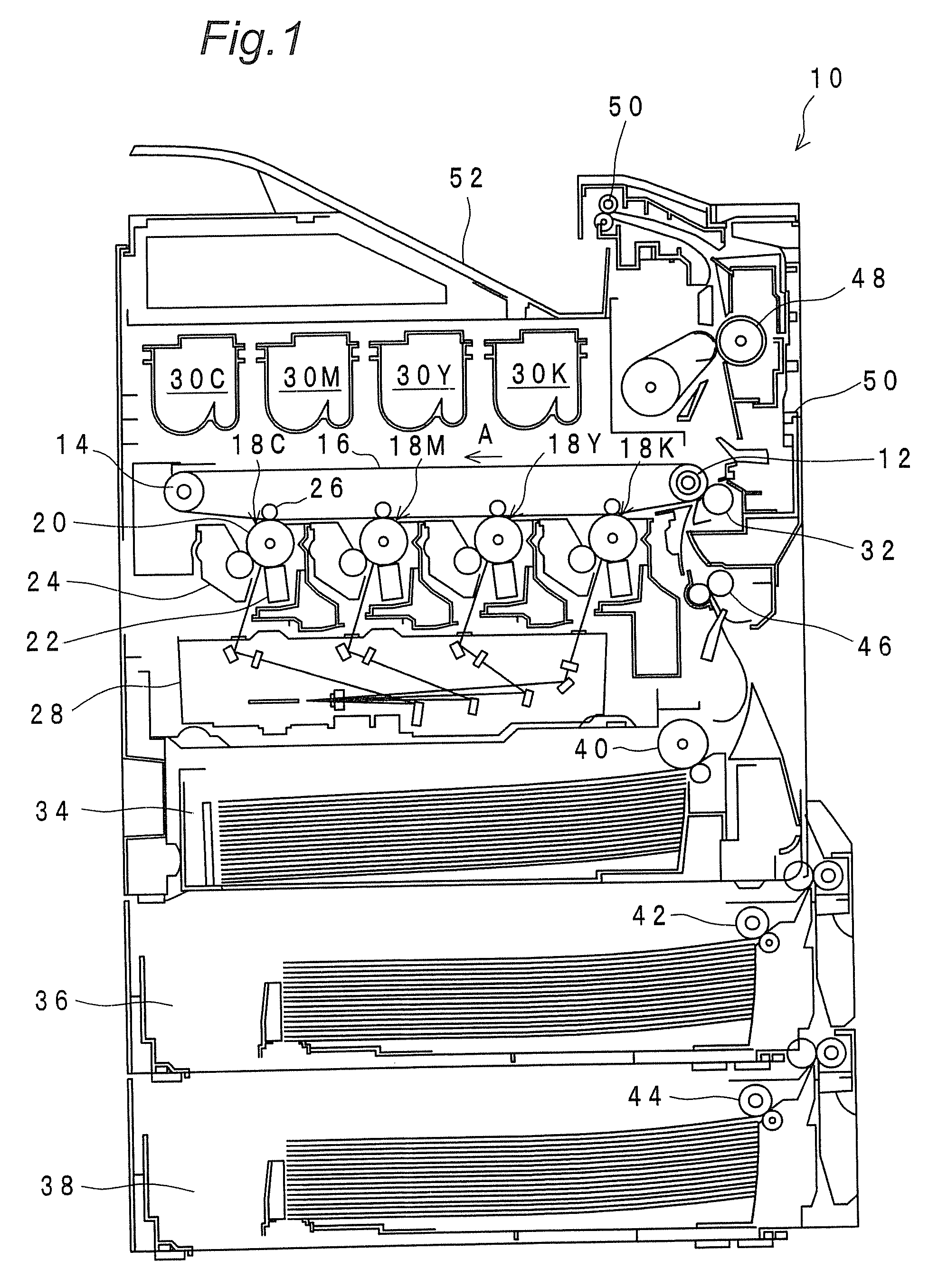
[0047]FIG. 1 is an overall structure view showing a color laser printer 10 in a most preferred embodiment of the present invention. The printer 10 has an endless film-like intermediate transfer belt 16 which is hung over two rollers 12, 14 disposed parallel at a specified distance and is rotationally driven in an arrow A direction.

[0048] Below the intermediate transfer belt 16, image forming units 18C, 18M, 18Y, 18K corresponding to four-color toners C (cyan), M (magenta), Y (yellow) and K (black) are juxtaposed. Since the respective image forming units 18C, 18M, 18Y, 18K share the same structure, their structure is described by taking the image forming unit 18C as an example.

[0049] The image forming unit 18C has a dram-like photoreceptor 20 which is rotationally driven in the state of being in contact with the intermediate transfer belt 16. Around the photoreceptor 20, a charging unit 22 for uniformly charging the surface of the photoreceptor 20, a development unit 24 for develop...


PUM


Abstract

An image forming apparatus of the present invention includes a first identification section for identifying whether a print target page in a print target document is color or monochrome and its page attribute, a second identification section for identifying a system speed during printing of an immediately preceding page of the print target page, a third identification section for identifying a presence of a subsequent page of the print target page and its page attribute, and a system speed determination section for selecting a print mode in conformity to a monochrome / color discrimination result based on an identification result in the first identification section and determining a system speed of the print target page based on the page attribute identified by the first identification section and identification results in the second and third identification sections.

Description

RELATED APPLICATION [0001] This application is based on Japanese Patent Application No. 2005-329617, the content of which is incorporated herein by reference. BACKGROUND OF THE INVENTION [0002] The present invention relates to an image forming apparatus such as color copiers and printers. [0003] Conventionally, so-called tandem-type color laser printers have large advantage of being able to process image data including monochrome pages and color pages both at the same print speed because latent image formation and toner image formation are executed independently by each of colors Y (yellow), M (magenta), C (cyan) and K (black). In the case of printing a document including both monochrome and color pages, printing all the pages in a color print mode causes increased load or wear of a color processing section, and therefore it is preferable to switch between a color print mode and a monochrome print mode depending on each page. [0004] However, depending of a mixture rate of color and ...

Claims


Application Information

Patent Timeline
IPC IPC(8): G03G15/00
CPCG03G15/01G03G15/6529G03G2215/00949
Inventor OOMINAMI, TAIICHISHIBATA, SEIJIIMOTO, TOMIKOMAEDA, HIROYUKIMEKADA, HIDEKIYAMAMOTO, YUICHI
Owner KONICA MINOLTA BUSINESS TECH INC
Learn More