Blind rivet method

a technology of blind rivets and rivets, which is applied in the direction of fastening means, screws, dowels, etc., can solve the problems of limiting the available workspace on the blind side of work pieces, and achieve the effect of increasing the diameter of the head and preventing it from becoming distorted

Active Publication Date: 2007-05-17
NEWFREY
View PDF99 Cites 7 Cited by
  • Summary
  • Abstract
  • Description
  • Claims
  • Application Information

AI Technical Summary

Benefits of technology

[0009] It is also preferred that the head diameter of the mandrel head is between 4% and 9% greater than an outer diameter of the tubular rivet body. For this reason, the rivet is intended to be inserted into a preformed hole extending through a workpiece / s which must have a diameter greater than this maximum head diameter and which is usually provided to have a diameter 10% greater than the body diameter. However, the hole diameter may lie in a range of 9% and 15% greater than the body diameter, dependent on the head diameter. This increased diameter of the head alleviates the possibility of the head being drawn into the rivet body during setting.
[0010] Furthermore, it is preferred that the mandrel head has an outer cylindrical diameter, usually co-axial with the rivet body, having an axial length of at least 1 mm, again to alleviate the possibility of the conically deformed body encompassing the mandrel head during the setting operation and, further, to prevent the head from becoming distorted (or “dished”) under the large loads applied thereto during a setting operation.
[0011] It is also preferred that the axial length of the rivet body will be between 25% and 55% greater than the grip thickness of such rivet, the grip thickness being defined as the combined thickness of the work pieces being joined together by this rivet and hence the thickness to be gripped thereby. This predefined rivet body length ensures that there is sufficient rivet body material to form an appropriate rivet joint and to flow into the preformed hole in the workpieces without resulting in excess rivet body material projecting excessively from the blind side of the connected work pieces once set.

Problems solved by technology

However, in both these conventional types of blind rivet, a defined or enlarged section of the blind rivet is maintained on the blind side of the work piece presenting a projection which may limit the available workspace on the blind side of the work pieces.
This is particularly relevant in the use of blind rivets to manufacture small cabinets, such as those used in the computer industry, whereby the internal projection of a set blind rivet may interfere with the placement of components within such cabinets.

Method used


Image

  • Blind rivet method
  • Blind rivet method

Examples


Embodiment Construction

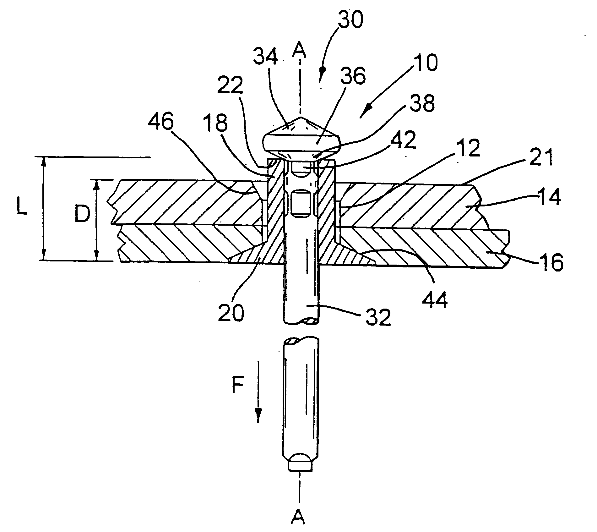
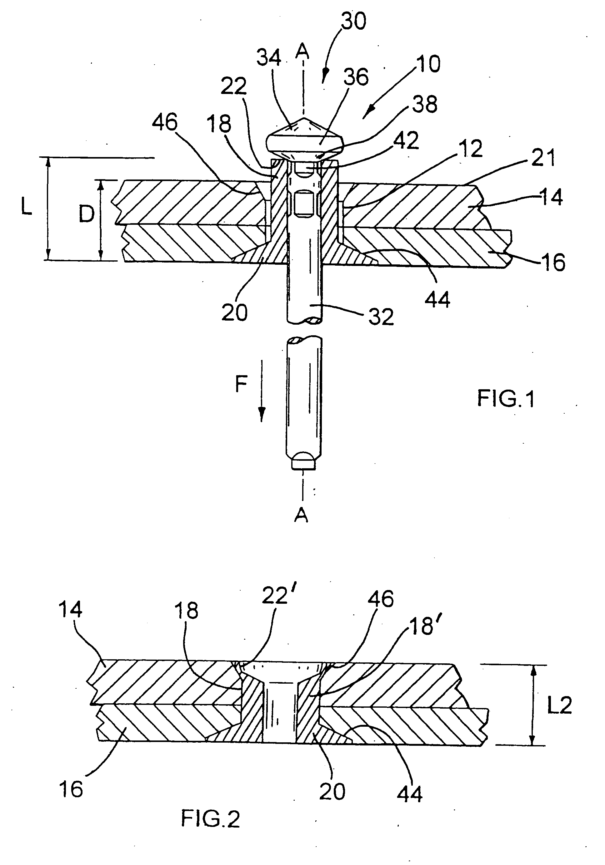
[0017] Referring now to FIG. 1, a blind rivet assembly 10 is shown inserted, but not set, in a preformed hole 12 extending between two work pieces 14 and 16. The rivet assembly 10 comprises a hollow tubular rivet body 18 having an enlarged counter-sunk flange 20, this counter-sunk head tapering inwards along an axis A of the rivet body for complimentary receipt within a pre-formed counter-sunk region 44 of the hole 12.

[0018] The remote tail end 22 of the rivet body 18, axially opposed to the flange 20, has a substantially flat end face extending perpendicular to the rivet axis A. The rivet body length L is predetermined to be between 25% and 55% greater than the combined depth D of the two work pieces 14 and 16. This depth D is commonly referred to as the grip thickness of a blind rivet—defined as the thickness of material to be gripped by the set rivet. In the present embodiment, depth L is approximately 30% greater than depth D. As is conventional for blind rivets, the assembly 1...


PUM

PropertyMeasurementUnit
angleaaaaaaaaaa
angleaaaaaaaaaa
angleaaaaaaaaaa

Abstract

There is provided a blind rivet comprising an axially extending hollow tubular body having a tail end face at one end and a pre-formed radially enlarged flange at the other end, together with a mandrel having a stem which extends co-axially though the body and having enlarged head adjacent the tail end of the body, the stem having a weakened region immediately adjacent the head, whereby the mandrel head having an outer diameter greater than an outer diameter of said body, usually by between 4% and 9%, and which has a uniform conical shoulder extending between said outer diameter of the head and the stem, so as to exert a setting force having an axial component for compressing the rivet body axially and an angular component effecting conical deformation of the tail end radially. There is also provided a method of fastening at least two workpieces using such a blind rivet, including providing the blind side of the workpieces with a countersunk region to accommodate the conically deformed tail end of the body after setting, substantially flush therewith.

Description

CROSS-REFERENCE TO RELATED APPLICATIONS [0001] This is a divisional application of U.S. Ser. No. 10 / 430,742, filed May 6, 2003, which claims priority to Great Britain Application No. 0210463.6, filed May 8, 2002, both of which are incorporated by reference herein.FIELD OF THE INVENTION [0002] The present invention is directed towards a blind rivet and more particularly to a blind rivet of the head break type whereby a mandrel head is ejected from the rivet body after setting. BACKGROUND OF THE INVENTION [0003] Conventional blind rivets comprise an outer tubular shell or body having an enlarged flange at one end, together with a mandrel associated therewith, such mandrel comprising a cylindrical stem extending through the tubular rivet body so as to be coaxial therewith, the stem having a radially enlarged head at one end for engagement with an end face (tail end) of the rivet body remote from the enlarged flange. The blind rivet is then passed through a preformed hole in a workpiece...

Claims


Application Information

Patent Timeline
Patent Type & Authority Applications(United States)
IPC IPC(8): F16B13/04F16B19/10
CPCF16B19/1054Y10T29/49943Y10T29/4992Y10T29/49956
Inventor JONES, STEVEN V.MORRIS, STEPHENHUGHES, JAMES
Owner NEWFREY
Why Eureka
Try Eureka