Wind energy installation

a technology for installing wind energy and wind turbines, which is applied in the direction of propellers, water-acting propulsive elements, artificial islands, etc., can solve the problems of increasing the problem of wind energy installation, affecting the life of components, and rotor blades and towers having a tendency to start oscillating,

Inactive Publication Date: 2007-05-17
DAUBNER & STOMMEL BAU WERK PLANUNG
View PDF0 Cites 48 Cited by
  • Summary
  • Abstract
  • Description
  • Claims
  • Application Information

AI Technical Summary

Benefits of technology

[0011] One object of the present invention is to specify a wind energy installation in which the abovementioned damaging movements/oscillations, in particular vibration, of the rotor blade and/or of other components, in

Problems solved by technology

Various components in wind energy installations such as these, in particular the rotor blades as well as the tower, have a tendency to start to oscillate, in particular as a result of external influences.
This is because the tower, which is arranged behind the rotor blade with respect to the wind direction, represents an obstruction for the wind.
Even with the normal dimensions of the individual components, in particular of the rotor blades, nowadays, oscillations such as these have a negative effect on the life of the components.
This problem is becoming more serious because of the trend to design wind energy installations with ever larger dimensions.
In the worst case, this can lead to catastrophic resonance (as is kn

Method used


Image

  • Wind energy installation
  • Wind energy installation
  • Wind energy installation

Examples


Embodiment Construction

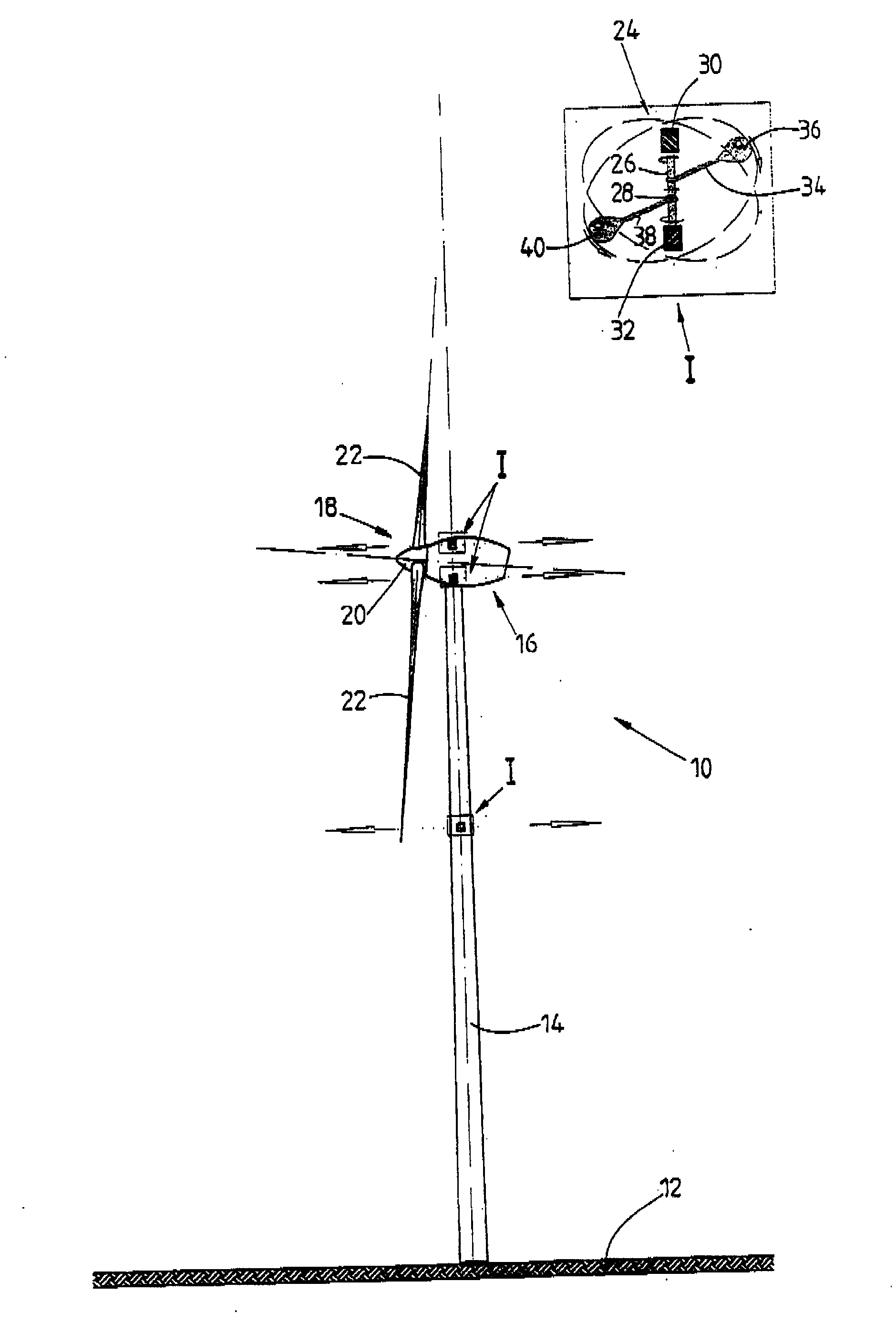
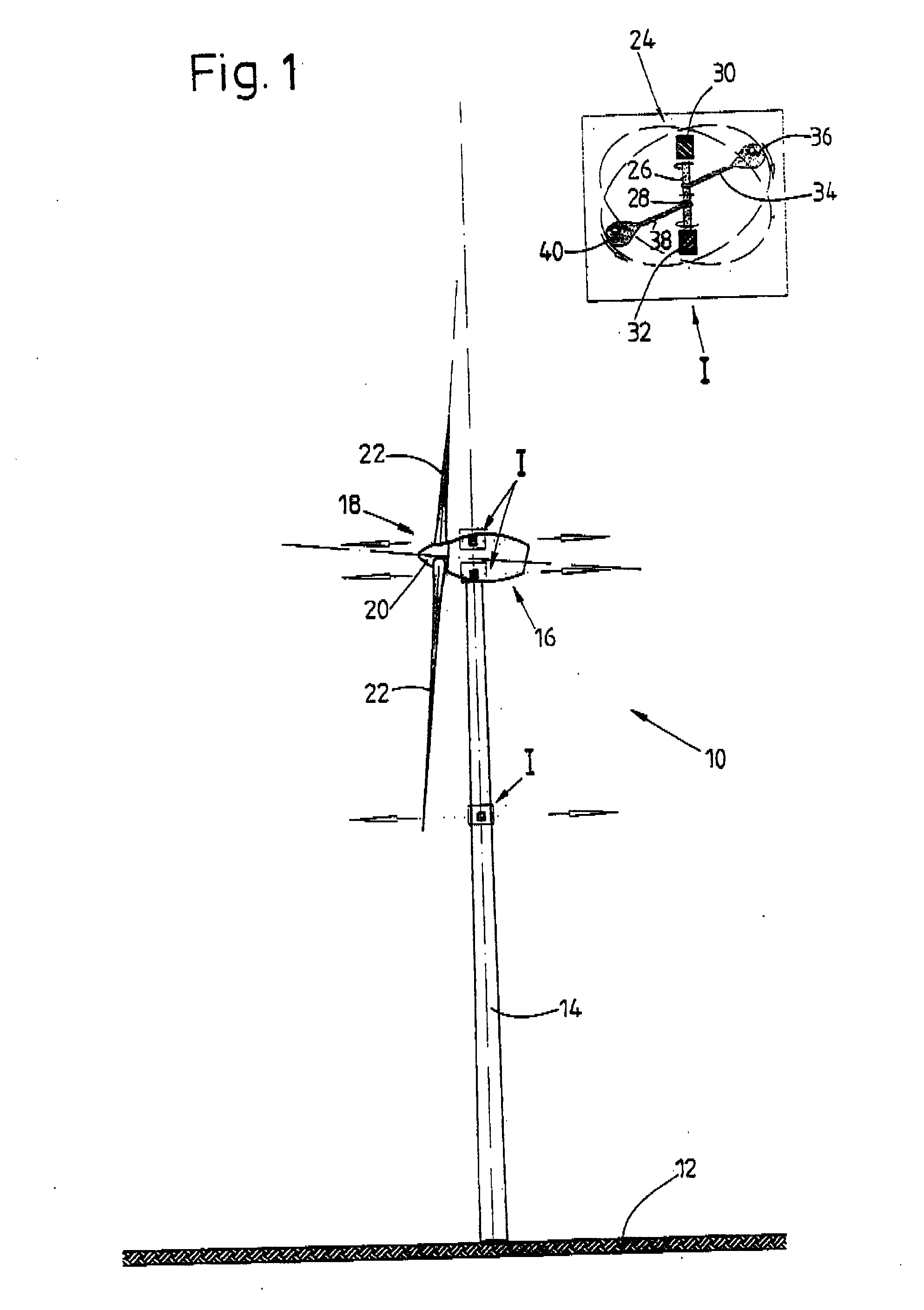
[0045]FIG. 1 illustrates a wind energy installation 10 which has a pod 16, which is arranged at the top of the tower, at the upper end of a vertical tower 14 which is arranged on a horizontal foundation 12. As those skilled in the art in this field will know, a wide range of embodiments are feasible for the detailed design of a tower for a wind energy installation. The invention is not, of course, restricted to the truncated-conical form of the tower 14 described in the drawing.

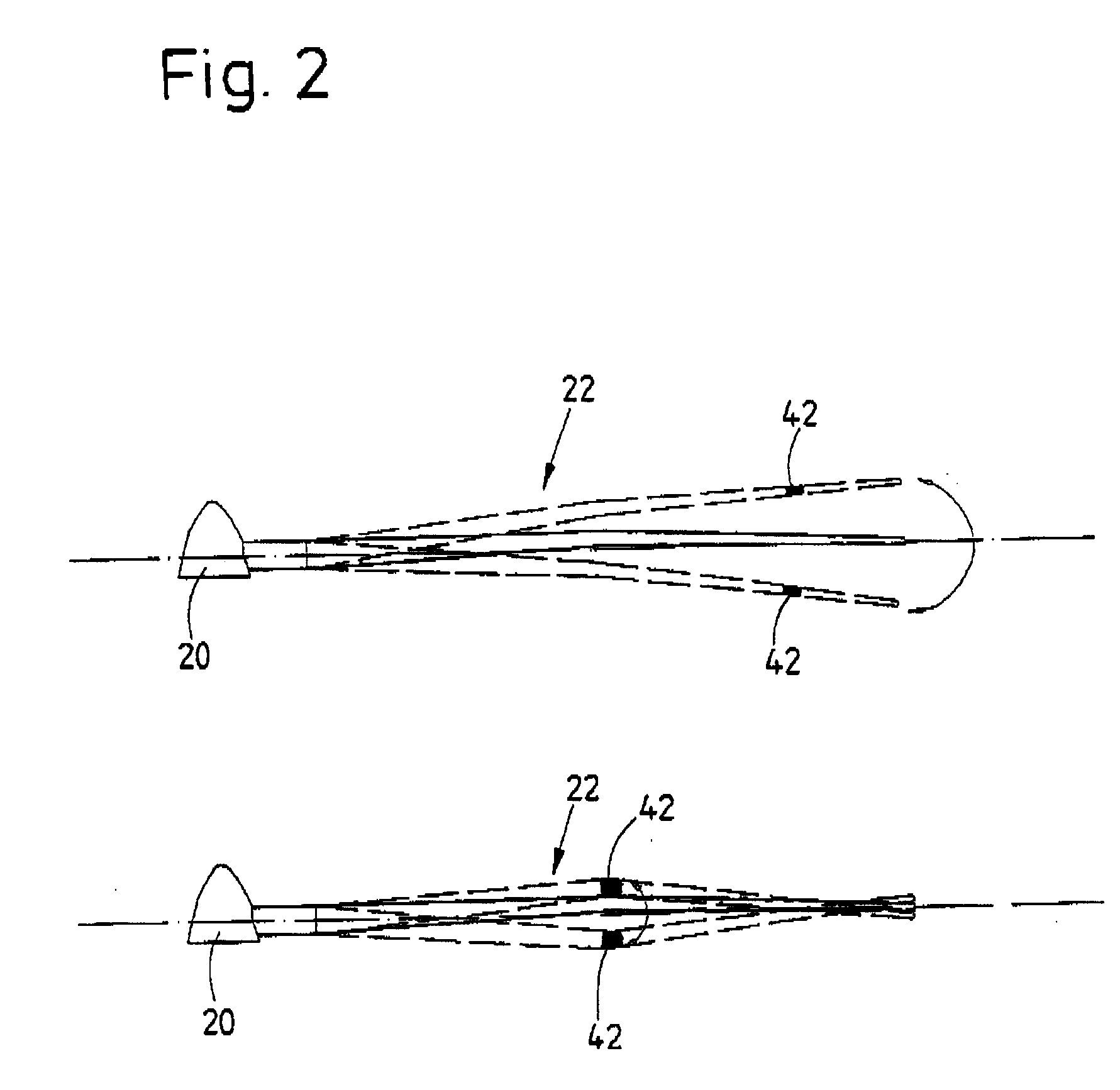
[0046] A rotor 18 is arranged at an end of the pod 16 facing the wind and has a hub 20. Three rotor blades 22 are connected to the hub 20, with the rotor blade roots of the rotor blades 22 being inserted into corresponding openings in the hub 20, and being connected to the hub 20 in a known manner.

[0047] The rotor 18 rotates about an axis which is inclined slightly upwards with respect to the horizontal. As soon as wind strikes the rotor blades 22, the rotor 18 is caused to rotate together with the rotor bl...


PUM


Abstract

The invention relates to a wind energy installation (10) having a rotor (18) which can be driven by wind and has at least one rotor blade (22), having a generator for conversion of the mechanical energy of the rotor (18) to electrical energy, and having a tower (14) on which the rotor (18) is arranged, in which the rotor blade (22) has one or more additional masses (36, 40) and/or active and/or passive oscillation dampers (24), which are designed in such a manner that movements of the rotor blade (22), in particular oscillations, which are initiated by external influences and are directed towards the tower or away from it are prevented and/or damped. The invention also relates to a method for operation of a wind energy installation, preferably of an off-shore wind energy installation, in which one or more components of the wind energy installation, preferably the tower (14), have opposing vibration applied to them in order to reduce/prevent sound waves which result from component vibration and disturb animals and/or people, which opposing vibration counteracts vibration (which produces sound) of the component (14), and reduces or prevents this component vibration.

Description

STATEMENT OF RELATED APPLICATIONS [0001] This application claims convention priority on German Patent Application No. 10 2005 053 145.8, having a filing date of 4 Nov. 2005, and German Patent Application No. 10 2006 022 266.0, having a filing date of 11 May 2006, both of which are incorporated herein by this reference. BACKGROUND OF THE INVENTION [0002] 1. Technical Field [0003] The present invention relates to a wind energy installation having a rotor which can be driven by wind and has at least one rotor blade, having a generator for conversion of the mechanical energy of the rotor to electrical energy, and having a tower on which the rotor is arranged. The present invention also relates to a method for operation of a wind energy installation such as this. [0004] 2. Related Art [0005] Various components in wind energy installations such as these, in particular the rotor blades as well as the tower, have a tendency to start to oscillate, in particular as a result of external influe...

Claims


Application Information

Patent Timeline
IPC IPC(8): B63H1/06
CPCE02B2017/0091F03D1/065F03D11/00F03D11/04F05B2240/95F05B2260/96F16F7/10F16F7/1005Y02E10/721Y02E10/727F03D80/00F03D13/20E02B17/027Y02E10/72F03D13/22
Inventor STOMMEL, MATTHIAS
Owner DAUBNER & STOMMEL BAU WERK PLANUNG
Why Eureka
Try Eureka