Eureka AIR delivers breakthrough ideas for toughest innovation challenges, trusted by R&D personnel around the world.

Substrate holding apparatus and polishing apparatus

a technology of holding apparatus and substrate, which is applied in the direction of manufacturing tools, grinding machine components, lapping machines, etc., can solve the problems of top ring assembly failure, and achieve the effect of higher accuracy

Active Publication Date: 2007-05-17
EBARA CORP
View PDF7 Cites 15 Cited by
  • Summary
  • Abstract
  • Description
  • Claims
  • Application Information

AI Technical Summary

Benefits of technology

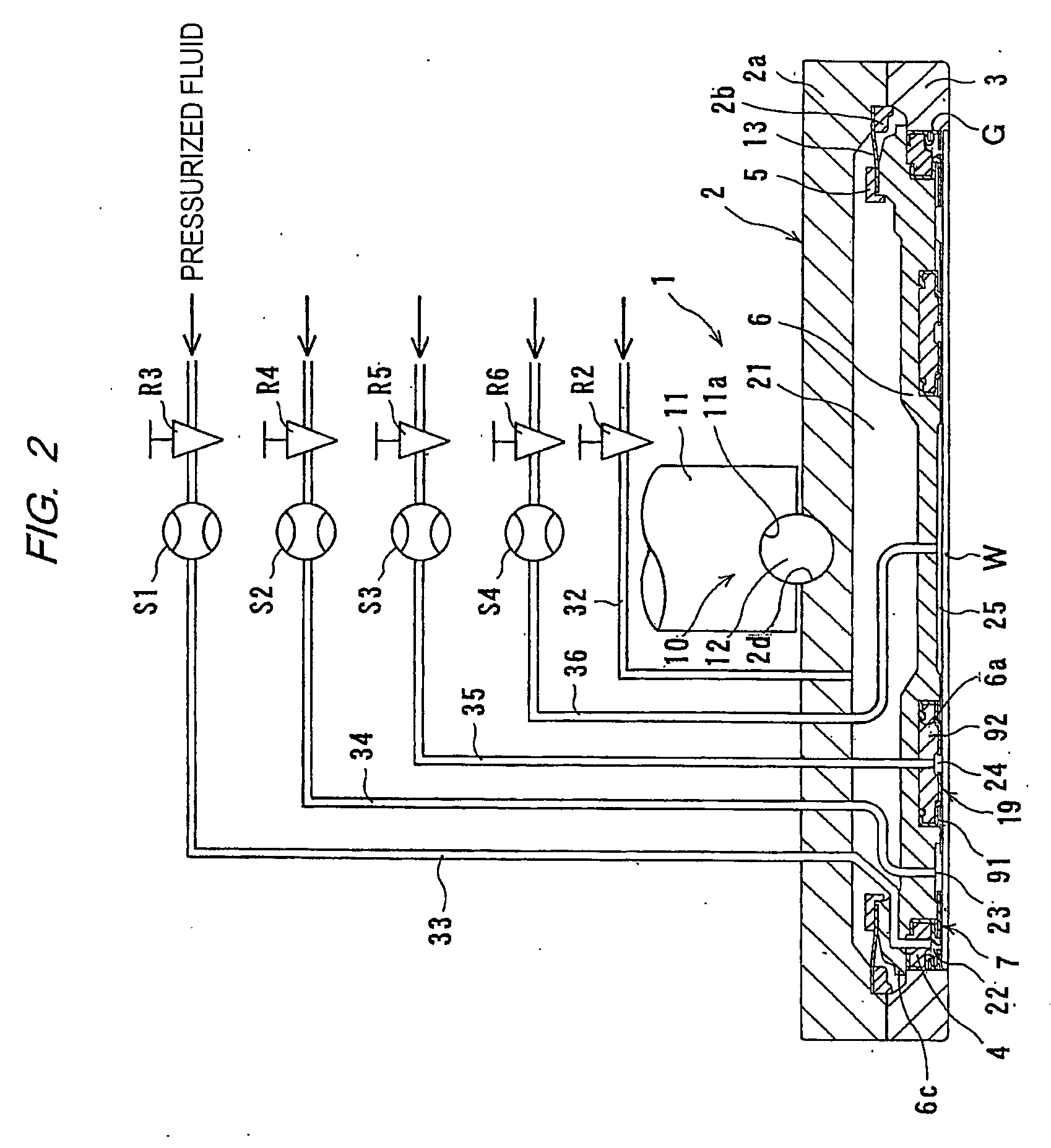
[0013] According to the first aspect of the present invention, a fluid leakage from pressure chambers or a fluid leakage between the substrate which is an object to be polished and a membrane (elastic membrane) can be detected by detecting a flowing state of a pressurized fluid. Therefore, a damage to the elastic membrane which defines the pressure chambers, an assembling failure of the top ring, or the like can be detected. Since the pressures in the pressure chambers can be kept under preset pressure levels, the possibility of damage to the substrate can be lowered. Furthermore, not only a fluid leakage from the pressure chambers but also a dislodgment of the substrate from the lower surface of the top ring during polishing can be detected, thus further reducing the possibility of damage to the substrate.
[0021] According to a preferred aspect of the present invention, polishing of the substrate is stopped when the sensors disposed respectively in two of the fluid passages for supplying the fluid to two adjacent ones of the pressure chambers detect respective fixed flow directions of the fluid.
[0026] According to a preferred aspect of the present invention, polishing of the substrate is stopped when the sensors disposed respectively in two of the fluid passages for supplying the fluid to two adjacent ones of the pressure chambers detect the same flow rate of the fluid.
[0028] According to a preferred aspect of the present invention, polishing of the substrate is stopped when the sensors disposed respectively in two of the fluid passages for supplying the fluid to two adjacent ones of the pressure chambers detect respective fixed flow directions of the fluid and respective fixed flow rates of the fluid.

Problems solved by technology

Therefore, a damage to the elastic membrane which defines the pressure chambers, an assembling failure of the top ring, or the like can be detected.

Method used


Image

  • Substrate holding apparatus and polishing apparatus
  • Substrate holding apparatus and polishing apparatus
  • Substrate holding apparatus and polishing apparatus

Examples


Embodiment Construction

[0040] A substrate holding apparatus and a polishing apparatus according to embodiments of the present invention will be described in detail below with reference to the drawings.

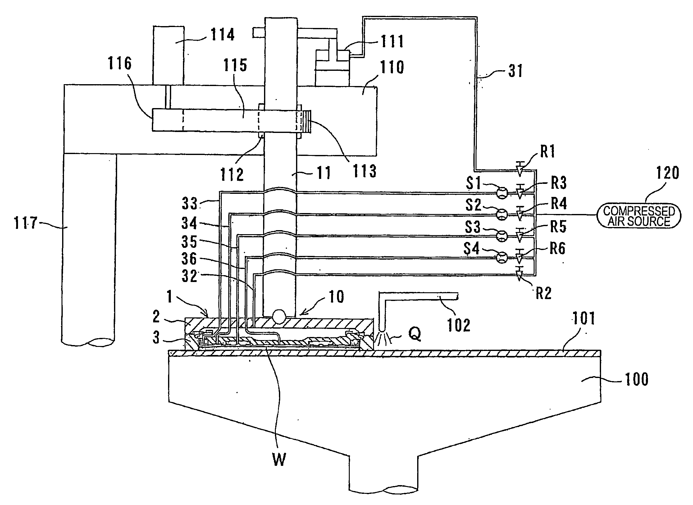
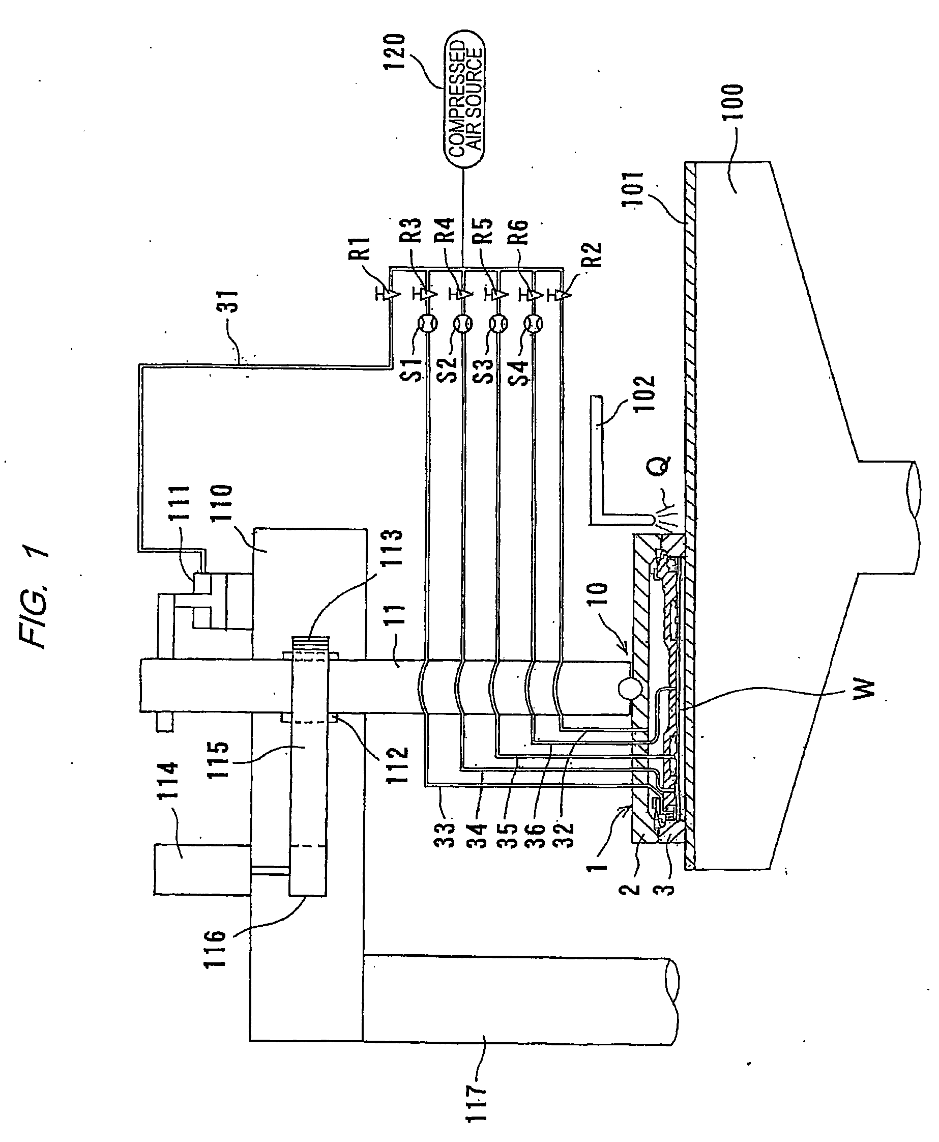
[0041]FIG. 1 is a cross-sectional view showing an entire arrangement of a polishing apparatus having a substrate holding apparatus according to the present invention. The substrate holding apparatus serves to hold a substrate such as a semiconductor wafer to be polished and to press the substrate against a polishing surface on a polishing table. As shown in FIG. 1, a polishing table 100 having a polishing pad 101 attached to an upper surface thereof is provided underneath a top ring 1 constituting a substrate holding apparatus according to the present invention. A polishing liquid supply nozzle 102 is provided above the polishing table 100, and a polishing liquid Q is supplied onto the polishing pad 101 on the polishing table 100 from the polishing liquid supply nozzle 102.

[0042] Various kinds of polishing...


PUM

PropertyMeasurementUnit
Pressureaaaaaaaaaa
Flow rateaaaaaaaaaa
Velocityaaaaaaaaaa

Abstract

A substrate holding apparatus holds a substrate such as a semiconductor and presses the substrate against a polishing surface. The substrate holding apparatus includes a top ring body (2) for holding the substrate, a plurality of fluid passages (33, 34, 35, 36) for supplying a fluid to a plurality of pressure chambers (22, 23, 24, 25) defined in the top ring body, and a plurality of sensors (S1, S2, S3, S4) disposed in the fluid passages, respectively, for detecting flowing states of the fluid which flows through the fluid passages.

Description

TECHNICAL FIELD [0001] The present invention relates to a substrate holding apparatus for holding a substrate to be polished and pressing the substrate against a polishing surface, and more particularly to a substrate holding apparatus for holding a substrate such as a semiconductor wafer in a polishing apparatus for polishing the substrate to a flat finish. The present invention also relates to a polishing apparatus having such a substrate holding apparatus. BACKGROUND ART [0002] In recent years, semiconductor devices have become more integrated, and structures of semiconductor elements have become more complicated. Further, the number of layers in multilayer interconnections used for a logical system has been increased. Accordingly, irregularities on a surface of a semiconductor device become increased, so that step heights on the surface of the semiconductor device tend to be larger. This is because, in a manufacturing process of a semiconductor device, a thin film is formed on a...

Claims


Application Information

Patent Timeline
IPC IPC(8): B24B49/00B24B37/04B24B37/30B24B37/32B24B49/16H01L21/304
CPCB24B37/30H01L21/6838H01L21/67092B24B49/16H01L21/304
Inventor TOGAWA, TETSUJINABEYA, OSAMU
Owner EBARA CORP
Why Eureka
Eureka Blog
Learn More