Assist transportation method and its device

a technology of transportation method and transportation area, which is applied in the direction of load-engaging elements, program-controlled manipulators, instruments, etc., can solve the problems of damage to the setting portion of heavy objects or heavy objects, and achieve the effect of efficiently corresponding to the change of assist conditions and easy setting of transportation area

Inactive Publication Date: 2007-05-17
HONDA MOTOR CO LTD
View PDF4 Cites 46 Cited by
  • Summary
  • Abstract
  • Description
  • Claims
  • Application Information

AI Technical Summary

Benefits of technology

[0023] According to the invention, because a transportation area and an assist condition every predetermined position of a transportation route and a transportation area and an assist condition are automatically set over the whole transportation route connecting predetermined positions, it is possible to easily set the transportation area. Therefore, it is possible to efficiently correspond to change of assist conditions due to change of transportation routes and change of transportation components.

Problems solved by technology

However in the case of the work assist disclosed in Japanese Patent Laid-Open No. 2000-84881, while a worker transports a heavy object or when the worker positions and sets the heavy object to a setting portion, even if the heavy object contacts with an obstacle, a reaction force generated in the heavy object due to the contact is not conducted to a worker operating the assist.
Therefore, there is a problem that the worker cannot detect that the heavy object contacts with the obstacle and thereby continues transportation work, and the heavy object or the heavy-object setting portion may be damaged.

Method used


Image

  • Assist transportation method and its device
  • Assist transportation method and its device
  • Assist transportation method and its device

Examples


first embodiment

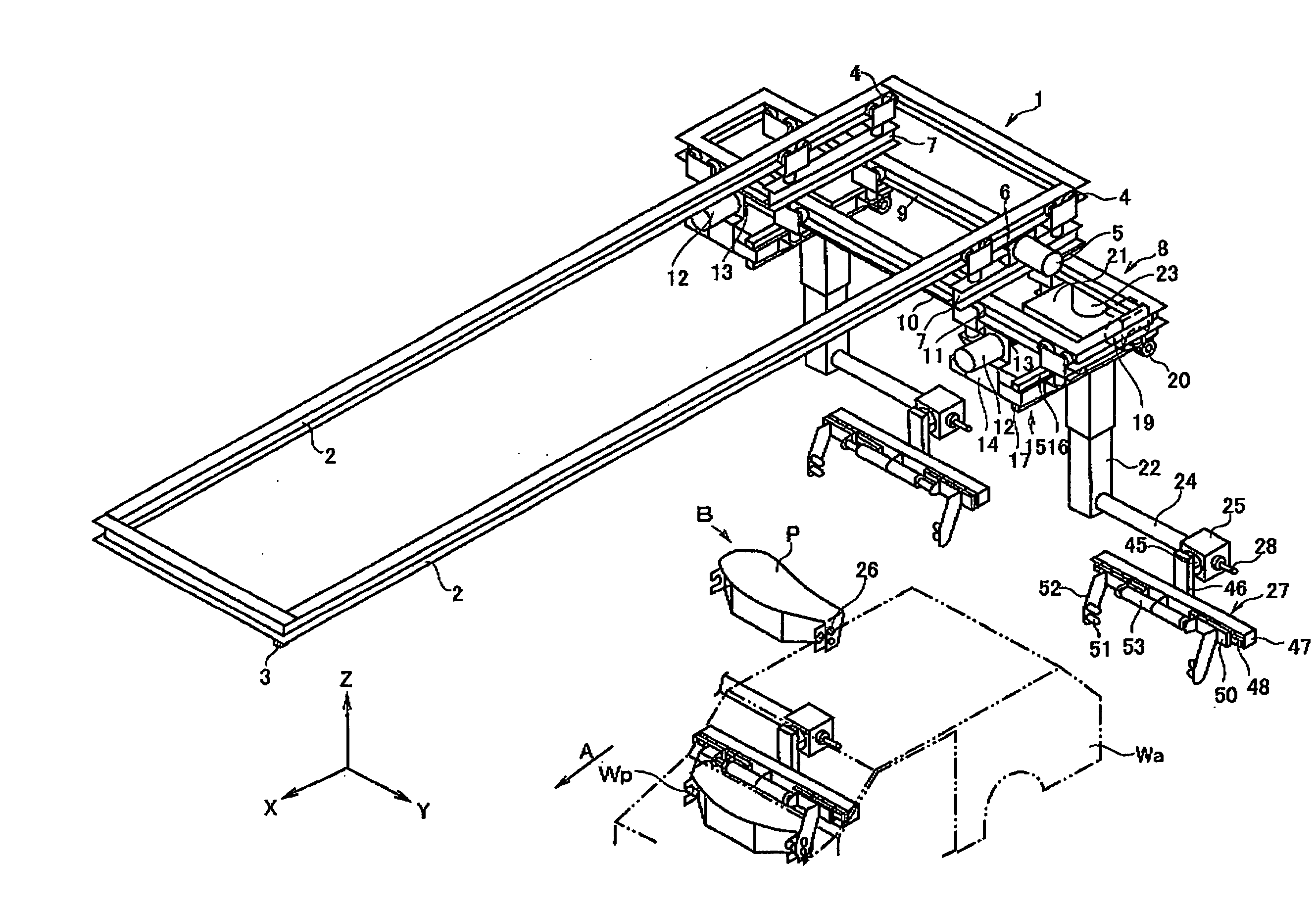
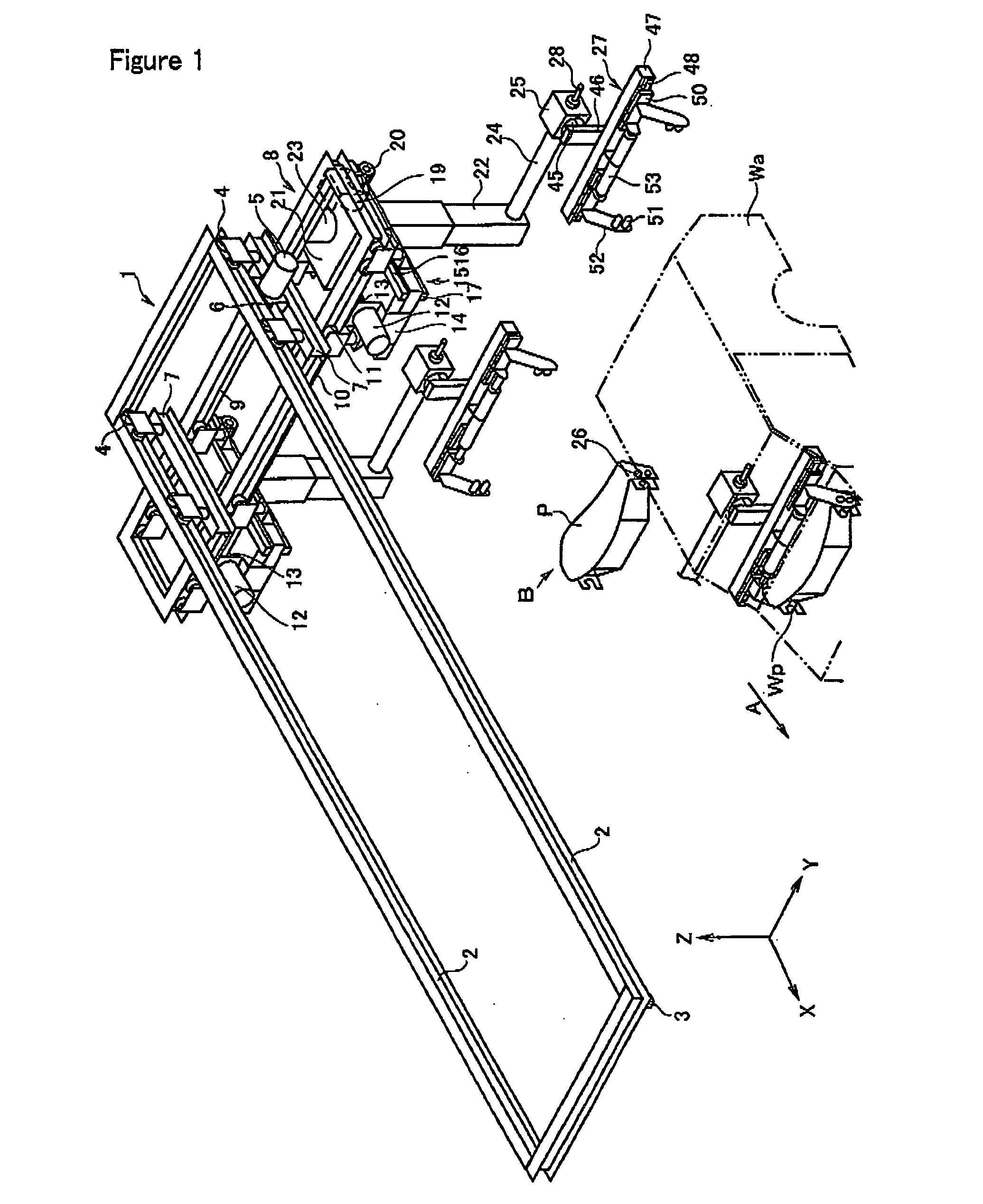
[0058] A first embodiment using an assist transportation method and its device of the present invention is constituted as described below. In FIG. 1, an assist transportation device shows two states, that is, a position (original position) for horizontally (Y direction) holding an instrument panel P of the vehicle body Wa and a position of setting the instrument panel P to the vehicle body Wa.

[0059] A first frame body 1 is set above the vehicle assembly line in parallel with (X direction) the vehicle assembly line. Two slide rails 2 and one rack 3 are set to the first frame body 1 in parallel with the vehicle assembly line. A plurality of rollers 4 are rotatably engaged with the two slide rails 2 and a pinion gear 6 set to a motor 5 is engaged with the rack 3. The rollers 4 and motor 5 are set to a support member 7. The motor 5 is a motor for synchronizing the assist transportation device with the vehicle body Wa.

[0060] Moreover, a second frame body 8 is connected to the rollers 4 ...

second embodiment

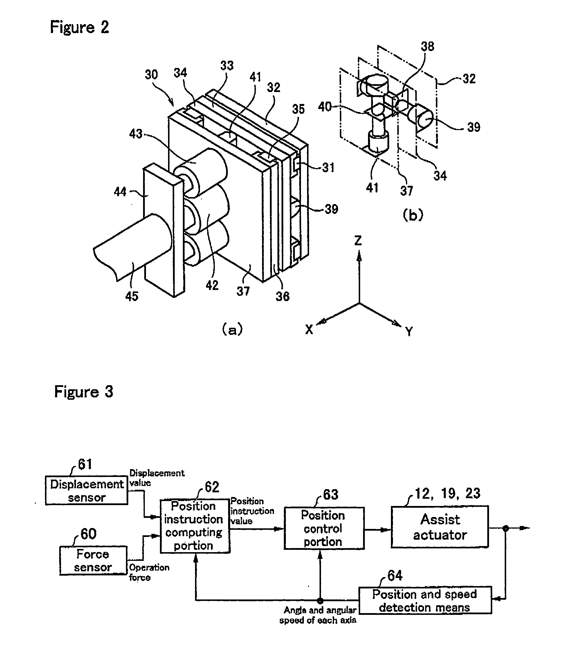
[0093] As shown in FIG. 9, a control system for power assist control in the second embodiment is constituted of displacement sensors 61 for detecting displacement values in orthogonal three-axis directions set to the floating mechanism 30, target value computing portion 65, control portion 66, motor (for Y axis) 12, motor (for X axis) 19, motor (for Z axis) 23 serving as assist driving actuators, and position and speed detection means 64 for detecting positions and speeds of the motors 12, 19 and 23.

[0094] As shown in FIG. 10, when a worker grips operation handles 28a and 28b and leads the instrument panel P held by the instrument panel holing means 27 in a desired direction, at least one of three displacement sensors 61 set to the floating mechanism 30 detects a displacement value and the displacement value is input to the target value computing portion 65.

[0095] Moreover, when the instrument panel P held by the instrument panel holding means 27 contacts with the vehicle body Wa o...

third embodiment

[0106] Then, an assist transportation method and its device of the present invention is applied to the door-glass elevating-regulator setting step portion of a vehicle door assembly line so that a door-glass elevating regulator can be efficiently set to a vehicle door to be pitch-fed.

[0107] That is, as shown in FIG. 11, the vehicle door assembly line 101 includes a door transportation line 102 for pitch-feeding a vehicle door W and a plurality of setting step portions 103 to be sequentially arranged from the upstream side to the downstream side of the door transportation line 102 and each setting component is set to the door W by the setting step portions 103.

[0108] Moreover, some of the setting step portions 103 are used as step portions for setting a door-glass elevating regulator R and the transportation means 104 shown in FIG. 12 is set to the step portion for setting the door-glass elevating regulator R.

[0109] In the door transportation line 102, a pair of right and left door...


PUM


Abstract

To provide an assist transportation device capable of properly communicating a reaction force to a worker due to contact without damaging any product and obstacle even if the product contacts the obstacle under work. The assist transportation device for reducing a load applied to the worker when the worker operates transportation means to transport an instrument panel P includes instrument panel holding means 27 for holding the instrument panel P, floating mechanism 30 set to the connection portion between the instrument panel holding means 27 and the transportation means, displacement sensor 61 for detecting the displacement value of the floating mechanism 30, and position instruction computing portion 62 for computing the displacement value detected by the displacement sensor 61 to calculate a reaction force, in which the reaction force is transferred to the worker operating the transportation means.

Description

TECHNICAL FIELD [0001] The present invention relates to an assist transportation method and its device for decreasing the load to a worker when the worker operates transportation means to transport a product. BACKGROUND ART [0002] Conventionally, known is a work assist to which impedance control is applied by which a worker can perform transportation work while the worker feels as if he / she transports a light weight object though a heavy one. The work assist is a power assist provided with first to eighth movable bodies for supporting a heavy object, actuators for moving the movable bodies, and a controller for controlling outputs of the actuators, detecting a force to be indirectly applied to the heavy object by a worker by a force sensor in order to transport the heavy object fixed to the eighth movable body by worker's way, controlling the first to eighth movable bodies in accordance with the information, and reducing the load to the worker (for example, refer to Japanese Patent ...

Claims


Application Information

Patent Timeline
Patent Type & Authority Applications(United States)
IPC IPC(8): B25J13/08B25J9/02B62D65/18B66C13/18
CPCB25J9/026B25J13/085B62D65/18B66C13/18
Inventor KONDO, TOSHIYUKINAKAJIMA, RYOYOSHIDA, SHINOZAWA, TETSUYASAKAI, YOSHIHARU
Owner HONDA MOTOR CO LTD
Why Eureka
Try Eureka