Gas sensor
a technology of gas sensor and sensor element, applied in the field of gas sensor, can solve problems such as the risk of damage to the sensor element, and achieve the effect of stably placed and favorable electrical conta
- Summary
- Abstract
- Description
- Claims
- Application Information
AI Technical Summary
Benefits of technology
Problems solved by technology
Method used
Image

Examples
first embodiment
[0050] A gas sensor of a first embodiment according to the present invention is described below in detail with reference to FIGS. 1 to 6.
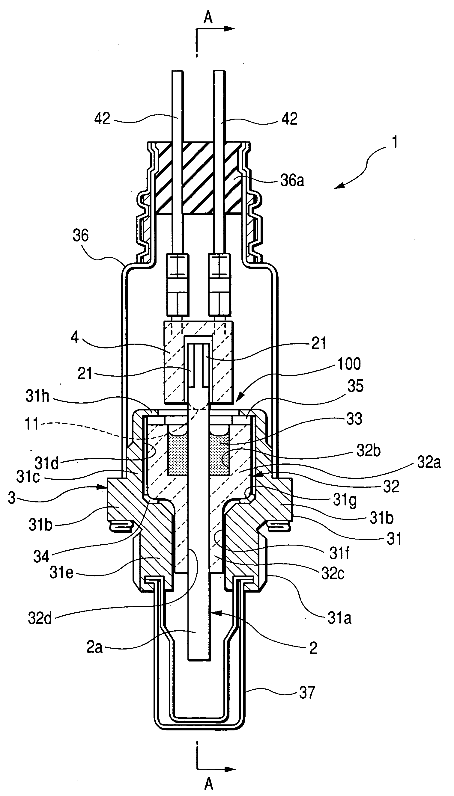
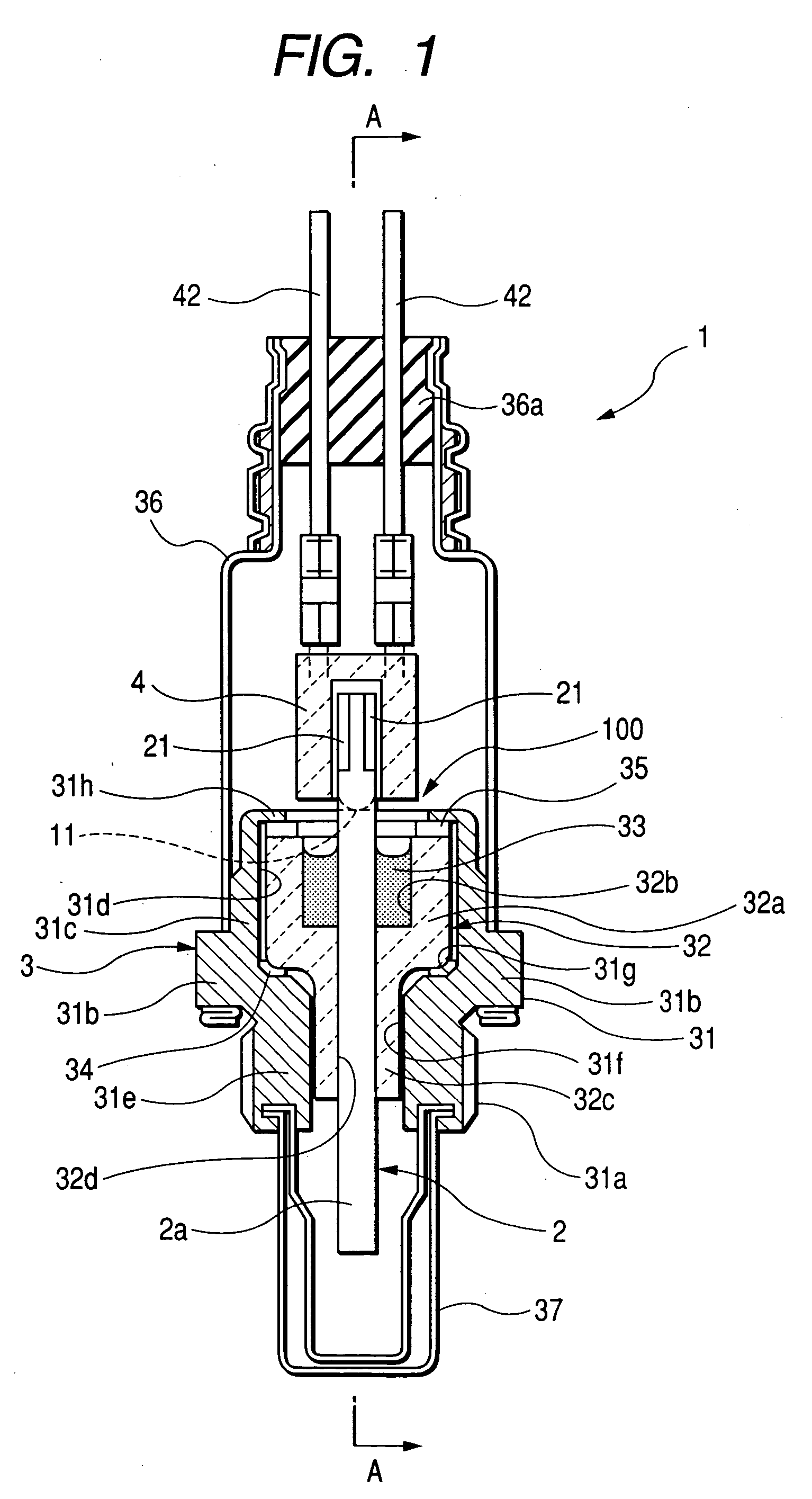
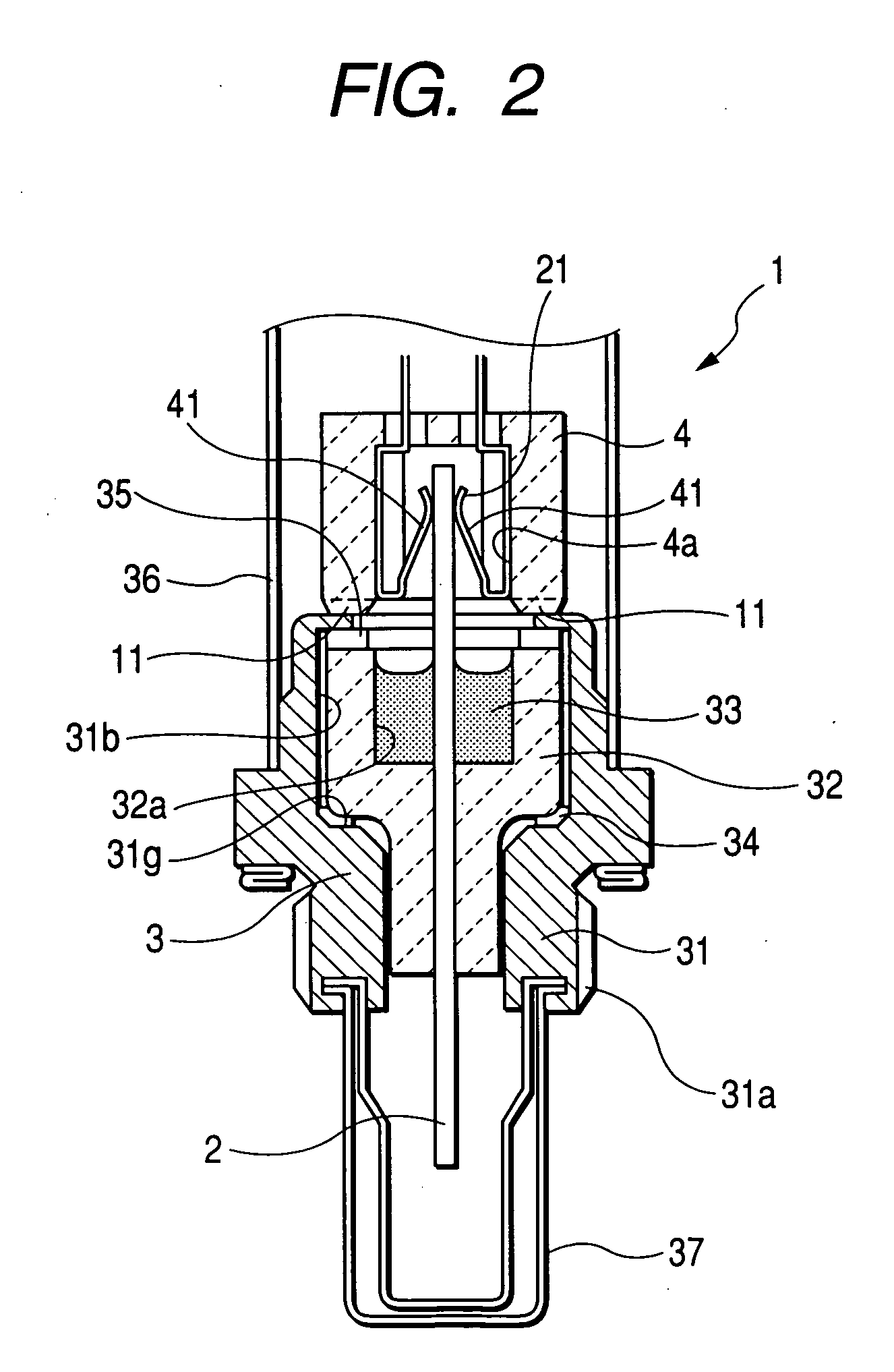
[0051] As shown in FIGS. 1 and 2, a gas sensor 1 of the present embodiment comprises a sensor element 2, formed in rectangular shape in cross section, which has a detecting portion 2a for detecting a concentration of specified gas contained in gas (hereinafter referred to as measuring gas) to be measured and a base end portion 2b, an element holder body 3 for inserting and holding the sensor element 2, and an atmosphere-side insulator 4 placed in a position to cover a base portion of the sensor element 2 in an area closer to a base end of the element holder body 3.
[0052] The element holder body 3 comprises a housing 31, formed with a threaded portion 31a available to be screwed into a flow passage area of measuring gas to allow the sensor element 2 to detect measuring gas, and an insulation member, that is, an element-side insulator 32 fixedly mo...
second embodiment
[0072] Next, a gas sensor 1A of a second embodiment according to the present invention is described below with reference to FIGS. 7 and 8. The gas sensor of the second embodiment is similar in structure to the gas sensor of the first embodiment except for several features and description is made with a focus on such features to omit redundant description.
[0073]FIG. 7 is a cross-sectional view of the gas sensor 1A of the second embodiment and FIG. 8 is a cross-sectional view of the gas sensor 1A, with the second embodiment representing a structure in which convexed portions 11A are formed on a base end of an element holder 3A.
[0074] With the gas sensor 1A of the second embodiment, an element holder insulator 32A, forming the element holder 3, has a cylindrical body 32a whose base end protrudes beyond a base end, that is, the caulked portion 31h of the housing 31A. Further, the cylindrical body 32a has a large diameter portion 321, formed between the first and second cylindrical por...
third embodiment
[0077] Next, a gas sensor 1B of a third embodiment according to the present invention is described below with reference to FIGS. 9 to 11. The gas sensor 1B of the third embodiment is similar in structure to the gas sensor 1 of the first embodiment except for several features and description is made with a focus on such features to omit redundant description.
[0078]FIG. 9 is a cross-sectional view of the gas sensor 1B of the third embodiment and FIG. 10 is a cross-sectional view, taken on line C-C of FIG. 9, of the gas sensor 1B, with the third embodiment representing a structure in which an atmosphere-side 4B and the sensor element 2. FIG. 11 is a cross-sectional view of the gas sensor 1B taken on line D-D of FIG. 10.
[0079] With the third embodiment, the gas sensor 1B includes an inner protection cylinder 361, coaxially disposed in the base end of the atmosphere-side cover 36 and supported with the base end of a housing 31B, which has one base end fixedly supported with an outer pe...
PUM
 Abstract
Description
Claims
Application Information
 - R&D
- Intellectual Property
- Life Sciences
- Materials
- Tech Scout
- Unparalleled Data Quality
- Higher Quality Content
- 60% Fewer Hallucinations
Browse by: Latest US Patents, China's latest patents, Technical Efficacy Thesaurus, Application Domain, Technology Topic, Popular Technical Reports.
© 2025 PatSnap. All rights reserved.Legal|Privacy policy|Modern Slavery Act Transparency Statement|Sitemap|About US| Contact US: help@patsnap.com