
Gas-fired cooking griddle

a technology of gas-fired cooking griddles and cooking griddles, which is applied in the direction of gaseous heating fuel, household stoves or ranges, heating types, etc., can solve the problems of confined griddle burners, inability to easily see the flame emanating from the burner, and difficulty in adjusting the griddle, so as to improve the heating accuracy and facilitate the use. , the effect of convenient us

Inactive Publication Date: 2007-05-24
PREMARK FEG L L C
View PDF19 Cites 25 Cited by
  • Summary
  • Abstract
  • Description
  • Claims
  • Application Information

AI Technical Summary

Benefits of technology

[0011] An advantage of the present invention is providing a griddle that is more easily adjusted and more precisely controlled than known griddle burner arrangements.
[0012] Another advantage of the present invention is providing a griddle burner assembly that is more conveniently used than known burner assemblies.
[0013] Still another advantage of the present invention is providing a griddle assembly with improved heating accuracy that can be provided more cost effectively than known thermostatically controlled griddle assemblies.
[0014] Other features and advantages of the invention will become apparent to those skilled in the art upon review of the following detailed description, claims and drawings in which like numerals are used to designate like features.

Problems solved by technology

Several problems and inconveniences have been experienced with known cooking griddles.
The griddle burner is confined in a substantially enclosed space, with limited viewing access thereto.
Accordingly, someone operating and adjusting the burner for the desired heating of the griddle cannot easily see the flame emanating from the burner.
Unlike open burners of cook tops, it is difficult for a cook to knowingly adjust the griddle burner to a desired heat setting.
The same is not true for griddle adjustment in which the burner cannot be seen easily.
This is especially problematic in commercial kitchens in which one setting may be desired early in the morning when preparing breakfast foods such as pancakes, eggs, bacon or the like and then another setting for the preparation of lunch or dinner foods including meats such as hamburgers, chicken breasts or the like.
In addition to limited viewability of the burner flame, adjustment of griddle burners has been difficult in that only limited rotation is available for turning the valve and adjusting the gas flow.
Rotation through only a narrow arc can cause a significant change in the gas flow, and a correspondingly significant change in burner output.
Accordingly, it has been difficult to control the temperature of griddles, with the control not being very precise.
However, such thermostatically controlled valves are expensive and subject to failure.

Method used


Image

  • Gas-fired cooking griddle
  • Gas-fired cooking griddle
  • Gas-fired cooking griddle

Examples


Embodiment Construction

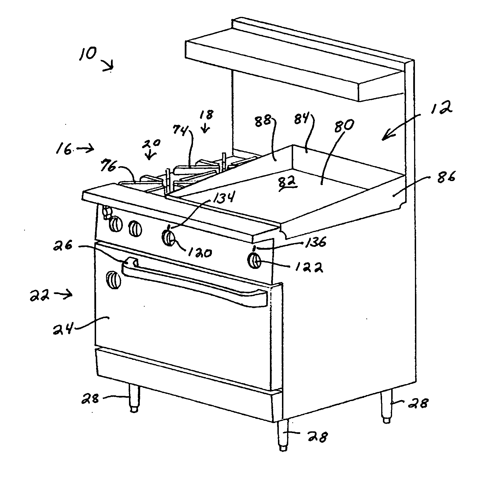
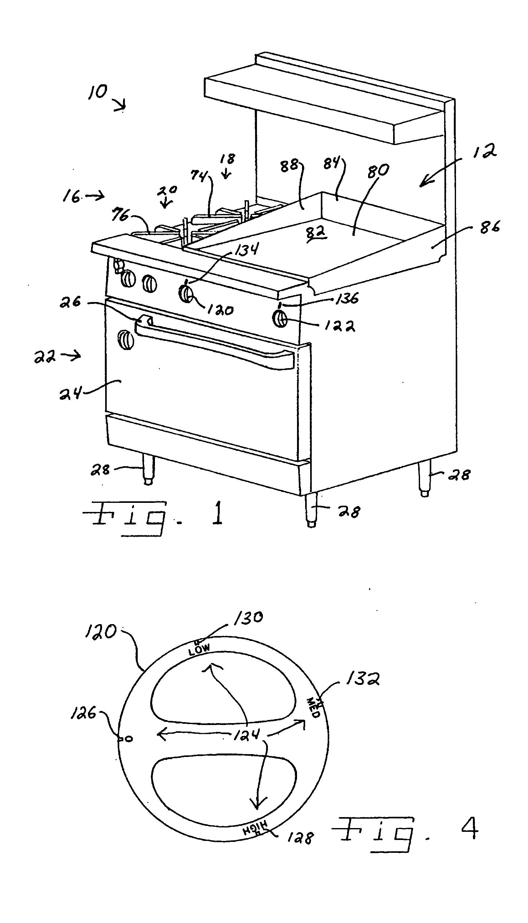
[0021] Referring now more specifically to the drawings and to FIG. 1 in particular, numeral 10 designates a gas-fired cooking range having a griddle area 12 and a gas circuit 14 (FIG. 3) in accordance with the present invention. The present invention can be used for various cooking appliances including commercial ranges, residential ranges and independent cooking griddles that are not part of a cooking range. The embodiment shown in FIG. 1 is merely an exemplar of an application of the present invention.

[0022] Griddle area 12 is part of a cook top 16 that further includes two open-flame cooking locations 18 and 20. Range 10 further includes an oven 22 accessed through a door 24 having a handle 26. Legs 28 support range 10, and can be pedestal-like supports as shown, or can be wheels or casters to facilitate moving range 10 for cleaning

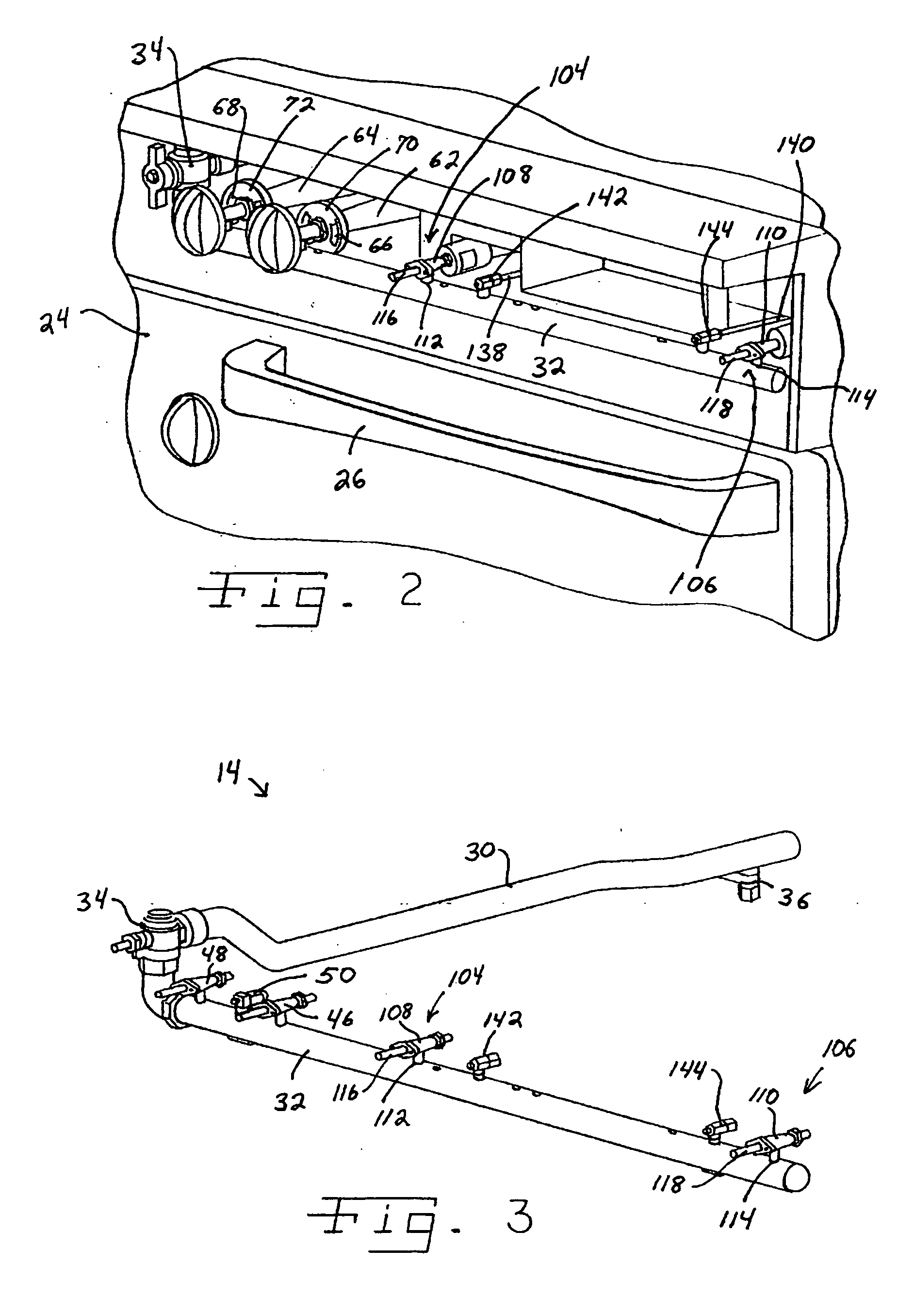
[0023] Gas circuit 14 includes a main gas line 30 connected to a gas fuel source such as, for example, a natural gas line from a natural gas utility...


PUM


Abstract

A cooking griddle has a burner with a valve controlling gas flow to the burner. The valve is rotatable through an increased arc for controlling flow of gas to the burner. A knob for rotating the valve includes indicia for indicating a relative position of the valve.

Description

FIELD OF THE INVENTION [0001] The present invention relates to gas fired cooking appliances, and, more particularly, the invention pertains to the control of a gas fired cooking griddle that may be independent or part of a cooking range. BACKGROUND OF THE INVENTION [0002] Gas fired cooking ranges are used in both residential and commercial kitchens. A basic design for a gas fired range includes a gas supply source, a manifold and one or more burner assemblies for receiving gas from the gas supply source via a connection to the manifold. It is also known to provide a cooking griddle as part of the cook top. It is further known to provide cooking griddles independent of gas fired, open flame cooking tops. [0003] A cooking griddle is known to provide a substantially continuous flat cooking surface on which food items can be placed directly for cooking. [0004] Whereas open flame cooking tops are generally used with cooking utensils such as pots or pans, a griddle can be used by placing ...

Claims


Application Information

Patent Timeline
IPC IPC(8): F24C15/32
CPCF24C3/124F24C3/126
Inventor CZAJKA, CHARLESJOHNSON, HAROLD JR.
Owner PREMARK FEG L L C
Learn More