
Hydraulic fracturing proppants and methods of use

a technology of hydraulic fracturing and proppants, applied in the field of proppants, can solve the problems of fractures prone to close, reservoir rock fractures or cracks, and each of these materials has drawbacks

Inactive Publication Date: 2007-05-24
ENGELHARD CORP
View PDF3 Cites 20 Cited by
  • Summary
  • Abstract
  • Description
  • Claims
  • Application Information

AI Technical Summary

Benefits of technology

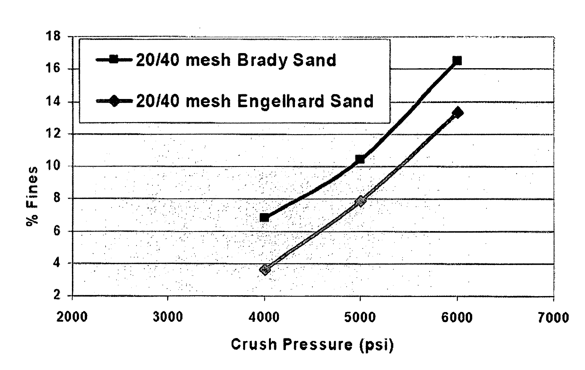
[0007] Embodiments of the invention relate to proppants and methods of use. The particles according to the various embodiments exhibit desirable crush resistance, sphericity, roundness, acid solubility, and turbidity, as determined by American Petroleum Institute Standard Recommended Practice 56 (RP-56). (See Recommended Practices for Testing Sand Used in Hydraulic Fracturing Operations, API Recommended Practice 56 Second Edition, December 1995, American Petroleum Institute). Other embodiments of the invention pertain to a method of propping open fractures during a hydraulic fracturing operation in a subterranean zone comprising placing the proppant particles of the various embodiments described herein in the fractures.
[0008] According to a first embodiment, a proppant comprises sand particles having a sand mesh size of 40/70, a median diameter of between about 0.20 mm and 0.40 mm, a crush resistance of less than about 10% fine particles by weight produced at a crush stress of about 5000 psi and turbidity of less than about 100 FTU, preferably less than about 50 FTU. In preferred embodiments, the 40/70 mesh sized proppant particles have a median particle diameter of about 0.32 mm, a crush resistance of less than about 5% maximum fine particles produced at a crush stress of about 5000 psi and a turbidity of less than about 20 FTU. In a particular embodiment, the 40/70 mesh sized proppant particles, the particles are sized such that between about 4 weight percent and 6 weight percent of the particles are retained on a mesh size 40 sieve, between about 20 weight percent and 25 weight percent of the particles are retained on a mesh size 45 sieve, between about 32 weight percent and 37 weight percent of the particles are retained on a mesh size 50 sieve, between about 32 and 37 weight percent of the particles are retained on a mesh size 60 sieve and between about 0.5 and 2 weight percent of the particles are retained on a mesh size 70 sieve. According to one embodiment, the 40/70 mesh sized proppant particles exhibit a sphericity exceeding about 0.75 and a roundness exceeding about 0.65. Another feature of the 40/70 sized proppant particles is that the specific gravity of the particles is between about 2.55 and 2.65. In a particular aspect, the 40/70 mesh sized particles have a median diameter of about 0.32 mm and being sized such that about 5.5 weight percent are retained on a 40 mesh sieve, about 23.3 weight percent are retained on a 45 mesh sieve, about 35.0 weight percent are retained on a 50 mesh sieve, about 34.8 weight percent are retained on 60 mesh sieve and about 1.4 weight percent are retained on a 70 mesh sieve.
[0009] In another embodiment, a proppant is provided which comprises sand particles having a 30/50 mesh size, a median diameter of between about 0.35 mm and 0.45 mm, a crush resistance of less than about 10% fine particles produced at a crush stress of about 4000 psi and a turbidity of less than about 100 FTU, preferably less than about 50 FTU. In a preferred embodiment, the median diameter of the 30/50 mesh sized particles is about 0.42 mm, have a crush resistance of less than about 3% fine particles produced at a crush stress of about 4000 psi and a turbidity of less than about 30 FTU. In a particular embodiment, the 30/50 mesh sized particles are sized such that between about 4 weight percent and 6 weight percent of the particles are retained on a mesh size 30 sieve, between about 20 weight percent and 25 weight percent of the particles are retained on a mesh size 35 sieve, between about 20 weight percent and 25 weight percent of the particles are retained on a mesh size 40 sieve, between about 20 and 25 weight percent of the particles are retained on a mesh size 45 sieve, between about 25 and 30 weight percent of the particles are retained on a mesh size 50 sieve, and between about 0.2 and 1 weight percent of the particles are retained on a mesh size 60 sieve, and the particles exhibiting a sphericity exceeding about 0.75 and a roundness exceeding about 0.70. According to one embodiment, another feature of 30/50 mesh sized proppant particles of is that the specific gravity of the particles is between about 2.55 and 2.65. According to a particular embodiment, the 30/50 mesh sized proppant particles are sized such that about 4.6 weight percent are retained on a 30 mesh sieve, about 22.8 weight percent are retained on a 35 mesh sieve, about 23.1 weight percent are retained on a 40 mesh sieve, about 22.1 weight percent are retained on 45 ...

Problems solved by technology

First, a fluid is injected into the well at a sufficient rate and pressure to rupture the formation and create a fracture or crack in the reservoir rock surrounding the well.
However, the fractures tend to close if they are not propped open.
Each of these materials has drawbacks.
For example, sand usually cannot withstand high pressures created by the forces closing the fractures.
It has been shown that at stresses of 10,000 psi and above, even the highest grade sand is inadequate because sand particles tend to disintegrate.
Proppants other than sand may be rather expensive for the use in large quantities necessary for well propping.
At stresses of 10,000 psi and above, even the highest grade sand has been inadequate.
The mining techniques and processing operations that have been used to acquire sand from the Bidahochi formation in the past has resulted in a proppant material having less desirable proppant properties than Brady sand and Ottawa sand.

Method used


Image

  • Hydraulic fracturing proppants and methods of use
  • Hydraulic fracturing proppants and methods of use
  • Hydraulic fracturing proppants and methods of use

Examples


Embodiment Construction

[0018] Before describing several exemplary embodiments of the invention, it is to be understood that the invention is not limited to the details of construction or process steps set forth in the following description. The invention is capable of other embodiments and of being practiced or being carried out in various ways.

[0019] Embodiments of the invention relate to novel hydraulic fracturing proppants and methods for their manufacture and use. According to certain embodiments, the methods involve injecting a proppant suspended in a carrier fluid into a subterranean formation. The proppant particles, when so injected, are deposited in the fracture to “prop” the adjacent walls apart so that the fracture is not closed.

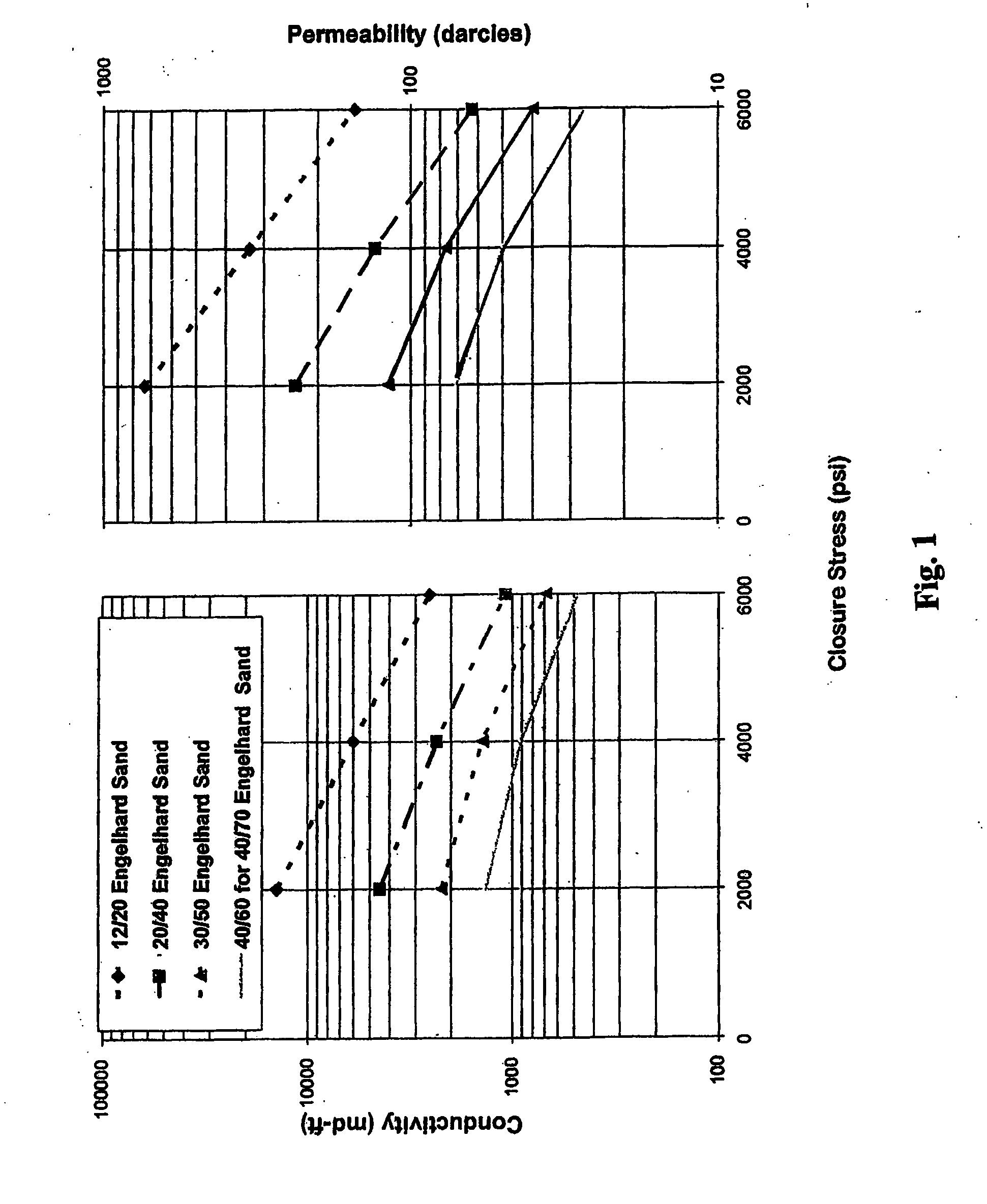
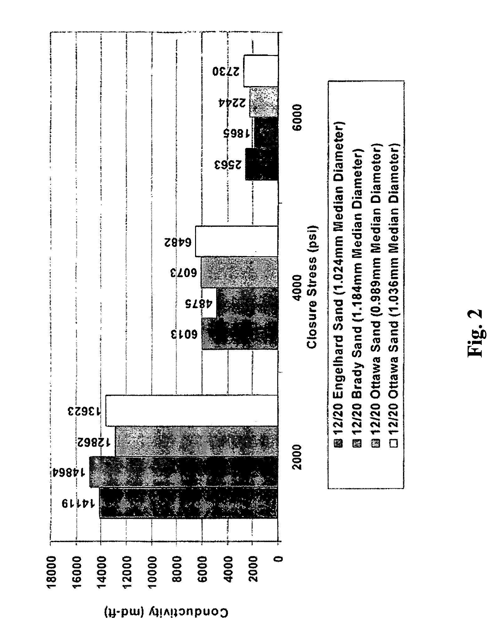
[0020] It is recognized in the art that particle size, particle size distribution, acid solubility, turbidity, crush resistance measured in quantity of fine particles, roundness and sphericity and proppant density all have an impact on fracture conductivity. Proppant ...


PUM


Abstract

Hydraulic fracturing proppants for use in propping fractures in subterranean well bores comprising sand particles and methods for their manufacture are described. According to one or more embodiments, the proppants exhibit a narrow particle size distribution, crush resistance, sphericity, roundness and turbidity. Methods for propping open fractures during a hydraulic fracturing operation are also described.

Description

FIELD OF THE INVENTION [0001] The present invention relates to proppants and methods of using proppants in hydraulic fracturing of subterranean formations surrounding oil wells, gas wells, and similar boreholes. BACKGROUND OF THE INVENTION [0002] Hydraulic fracturing is a technique designed to increase the productivity of a well, for example, an oil well or gas well, by creating highly conductive fractures or channels in the oil or gas producing formation surrounding the well. A hydraulic fracturing process normally involves two steps. First, a fluid is injected into the well at a sufficient rate and pressure to rupture the formation and create a fracture or crack in the reservoir rock surrounding the well. As a result, channels with high liquid conductivity are created from the wellbore into the formation. However, the fractures tend to close if they are not propped open. Accordingly, during formation of the fracture or after the fracture has been formed, a particulate material, wh...

Claims


Application Information

Patent Timeline
IPC IPC(8): E21B43/267
CPCC09K8/80
Inventor KAZI, M. SHAHJAHAN
Owner ENGELHARD CORP
Learn More