
Device for Sealing a Rotating Shaft Penetrating a Housing Wall

a technology for sealing devices and rotating shafts, which is applied in the direction of engine sealing, leakage prevention, engine components, etc., can solve the problems of increased hydrogen consumption, increased eccentricities of sealing rings, and inability to realize self-centering action, so as to improve the sealing function and the carrying capacity of sealing rings. , the effect of improving the sealing ring of the sealing devi

Inactive Publication Date: 2007-05-24
GENERAL ELECTRIC TECH GMBH
View PDF44 Cites 9 Cited by
  • Summary
  • Abstract
  • Description
  • Claims
  • Application Information

AI Technical Summary

Benefits of technology

[0010] It is an object of the present invention to improve the sealing ring of a sealing device of the aforementioned kind in such a way that the sealing function and the carrying capacity of the sealing ring are improved.
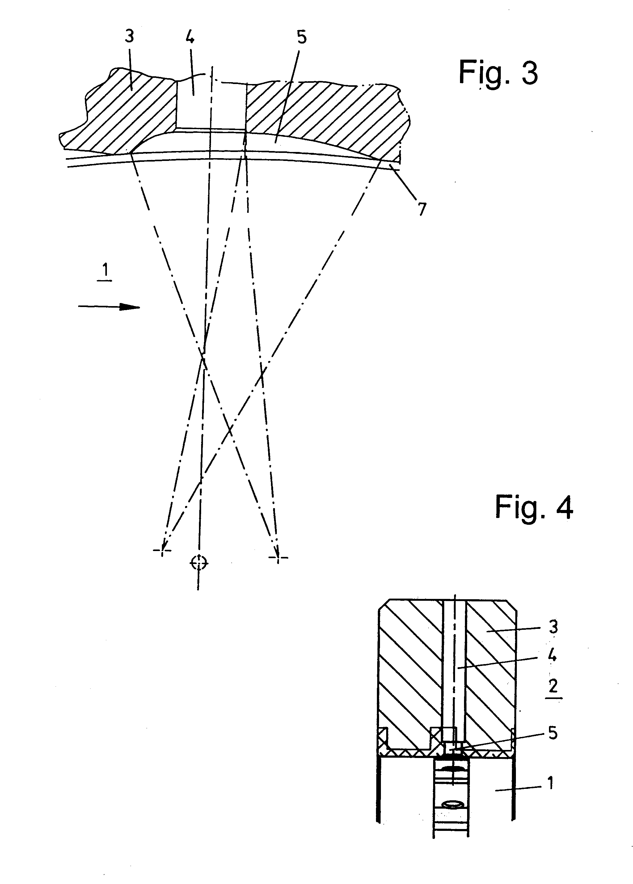
[0012] In this way, a sealing device with a special sealing ring is provided that is characterized by improved properties. For example, wear and oscillations are only minimal and the hydrogen consumption is reduced to a minimum. The basic idea of the sealing ring according to the invention resides in that the pocket-shaped recesses, viewed in the axial direction of the shaft, are not continuous but instead the pocket-shaped recesses have in the area of one sealing ring side or sealing ring plane a boundary wall. For laterally closing off the pocket-shaped recesses in the sealing ring a boundary stay is provided. The boundary stay is a concentric ring on one (flat) side of the sealing ring. The inner wall surface of the boundary wall of the pocket-shaped recess defines together with the outer wall surface of the shaft a wedge-shaped sealing gap in which the supplied sealing oil is located. In this connection, the sealing ring according to the invention has the advantage that no change in regard to the outer dimensions and no change of the nominal lubricant gap size are required. Moreover, a circumferential central groove at the center is provided primarily for generating two sealing wedges toward the air side and toward the hydrogen side. By means of this circumferential groove about the entire circumference of the sealing ring or the entire circumference of the shaft an oil film is provided in particular also at those locations where the sealing ring rests immediately against the shaft. In particular, the circumferential groove makes available a homogenous, uniformly distributed oil film for the pockets. Accordingly, with this circumferential central grove at the center together with the pockets, the complete sealing function and carrying capacity are ensured at all times. The center groove and the pocket-shaped recesses take over the complete sealing function and carrying capacity. The special characteristic of the sealing ring according to the invention is thus the configuration of the sealing surface of the shaft seal. As a whole, the wear is eliminated as well as side-swiping of the ring that leads to oscillations. As already mentioned supra, the hydrogen consumption can also be minimized and the hydrogen purity can be increased.
[0013] According to another embodiment, the sealing action is realized on that side of the pocket-shaped recesses where, relative to the oil pressure, the greater differential pressure is present. This has the advantage that leakage at this separation plane of the media is reduced to a minimum.
[0017] In an alternative embodiment, about the inner circumference of the sealing ring several coaxially spaced-apart circles of circumferential groove and pocket-shaped recesses are provided, i.e., several sealing circles are provided and spaced from one another coaxially. The circumferential grooves are coaxially spaced from one another and in these circumferential grooves the pocket-shaped recesses are formed. By providing several sealing circles, the sealing action of the sealing ring is improved.

Problems solved by technology

However, for a completely centered ring with constant gap size, a self-centering action cannot be realized.
This results in increased eccentricities of the sealing ring.
This causes irregular heating, thermal buckling, increased hydrogen consumption, lower hydrogen purity as well as generally increased wear.
The disadvantage of the sealing ring used in this sealing device resides in that the pocket-shaped recesses in the axial direction of the shaft are configured to be continuous, i.e., they extend from one side of the sealing ring to the other side of the sealing ring.
The result is that the effect of stabilization and self-centering cannot be completely realized.

Method used


Image

  • Device for Sealing a Rotating Shaft Penetrating a Housing Wall
  • Device for Sealing a Rotating Shaft Penetrating a Housing Wall
  • Device for Sealing a Rotating Shaft Penetrating a Housing Wall

Examples


Embodiment Construction

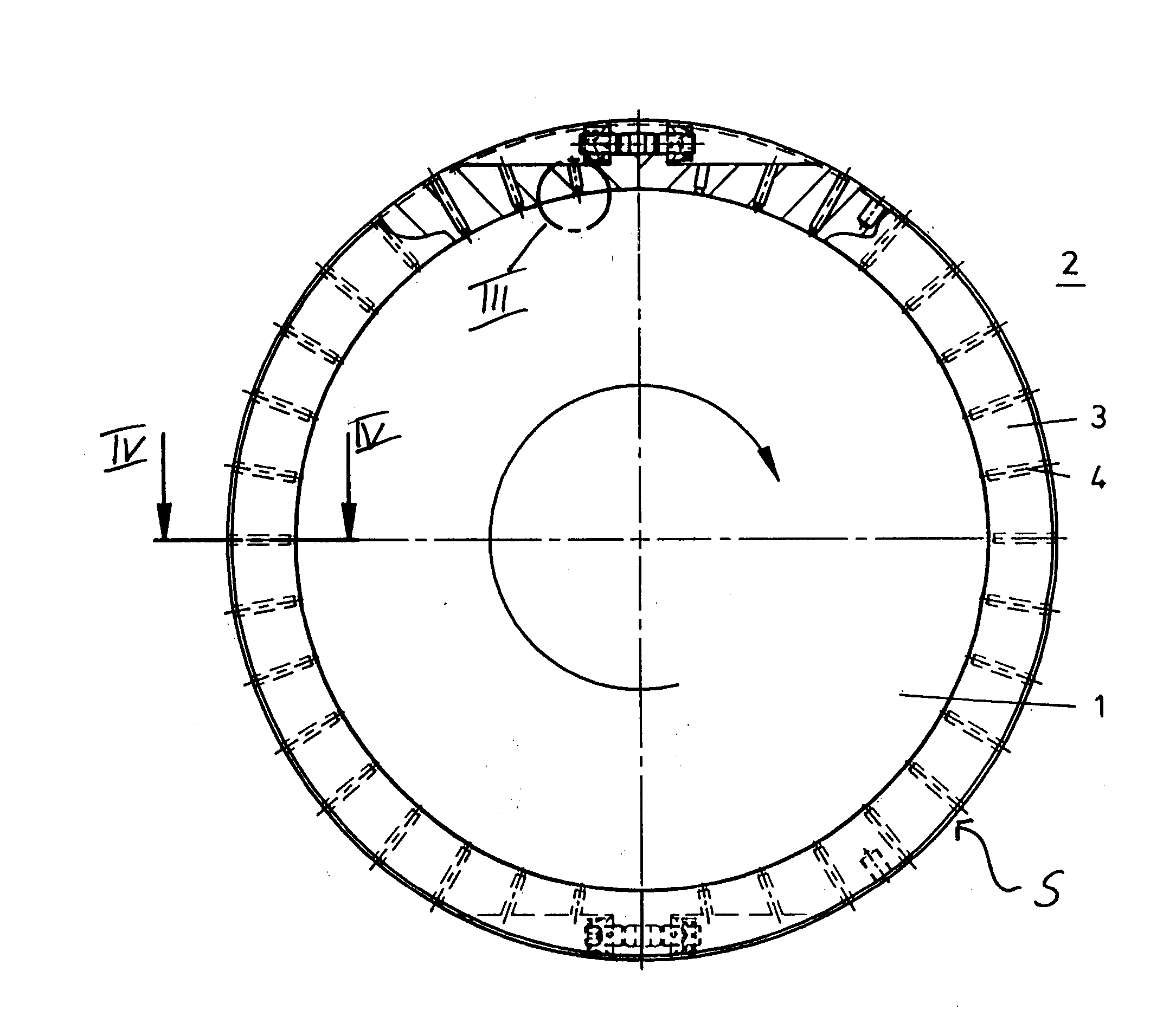
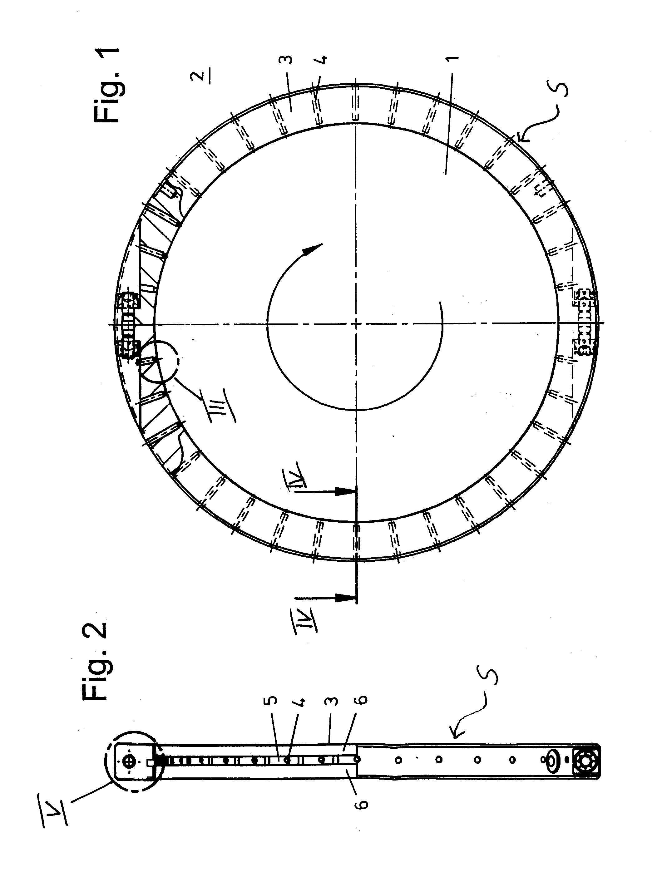
[0029] The illustrated embodiments concern a turbo generator in which the shaft 1 of the rotor penetrates a housing wall 2 and is rotatably supported therein. On one housing side of the housing wall 2 there is air (outside of the housing) and on the other housing side of the housing wall 2 there is hydrogen (in the interior of the housing).

[0030] Between the housing wall 2 and the shaft 1 there is a seal S comprising a sealing ring 3 that is connected fixedly to the housing wall 2. The sealing ring 3 has several sealing oil supply bores 4 that extend radially and are distributed about the circumference of the sealing ring. They open radially at the inner side if the sealing ring inside a pocket-shaped recess 5, respectively. As shown in FIG. 3, this pocket-shaped recess 5 has such a profile that, viewed in the rotary direction of the shaft 1, it is wedge-shaped.

[0031] On both sides of the sealing ring 3, the pocket-shaped recesses 5 are delimited by a circumferentially extending b...


PUM


Abstract

A device for sealing a rotating shaft that penetrates a stationary housing wall has a sealing ring fastened to the housing wall and arranged between the housing wall and a shaft. The sealing ring has sealing oil supply bores supplying sealing oil into a sealing gap formed between an inner wall surface of the sealing ring and an outer wall surface of the shaft. The inner wall surface has pocket-shaped recesses where the sealing oil supply bores open. The pocket-shaped recesses extend in the circumferential direction of the sealing ring. The inner wall of the sealing ring has at least one circumferential boundary stay that delimits and seals the pocket-shaped recesses in an axial direction of the sealing ring toward the first or second housing side. The inner wall surface of the sealing ring has a circumferential groove that connects the pocket-shaped recesses to one another.

Description

BACKGROUND OF THE INVENTION [0001] The invention relates to a device for sealing a rotating shaft penetrating a stationary housing wall relative to the two housing sides. The device comprises a sealing ring arranged between the housing wall and the shaft and fixedly connected to the housing wall. The device also comprises means for supplying sealing oil into the sealing gap between the inner wall surface of the sealing ring and the outer wall surface of the shaft, wherein the sealing ring in its sealing surface in the area of the means for supplying sealing oil has pocket-shaped recesses extending in the circumferential direction. The pocket-shaped recesses of the sealing ring are closed off at least on one side of the sealing ring and sealed relative to the adjoining space of the correlated housing side by a circumferential boundary stay. [0002] A special field of application of the invention are so-called turbo generators for generating electric energy. In turbo generators having ...

Claims


Application Information

Patent Timeline
IPC IPC(8): F16J15/44
CPCF16J15/442F16J15/443
Inventor SCHOLLHORN, KARL
Owner GENERAL ELECTRIC TECH GMBH
Learn More