Systems and methods for directing a current

a current path and current technology, applied in the direction of electrical generator control, lighting conductor installation, connection to earth, etc., can solve the problems of damage to components, major costly repairs of components, and current propagation through the rotor blade and into the components

Inactive Publication Date: 2007-05-24
GENERAL ELECTRIC CO
View PDF7 Cites 18 Cited by
  • Summary
  • Abstract
  • Description
  • Claims
  • Application Information

AI Technical Summary

Problems solved by technology

In an event of the lightning strikes to the rotor blade, there is a risk that a path of the current will propagate through the rotor blade and into the com...

Method used


Image

  • Systems and methods for directing a current
  • Systems and methods for directing a current
  • Systems and methods for directing a current

Examples


Embodiment Construction

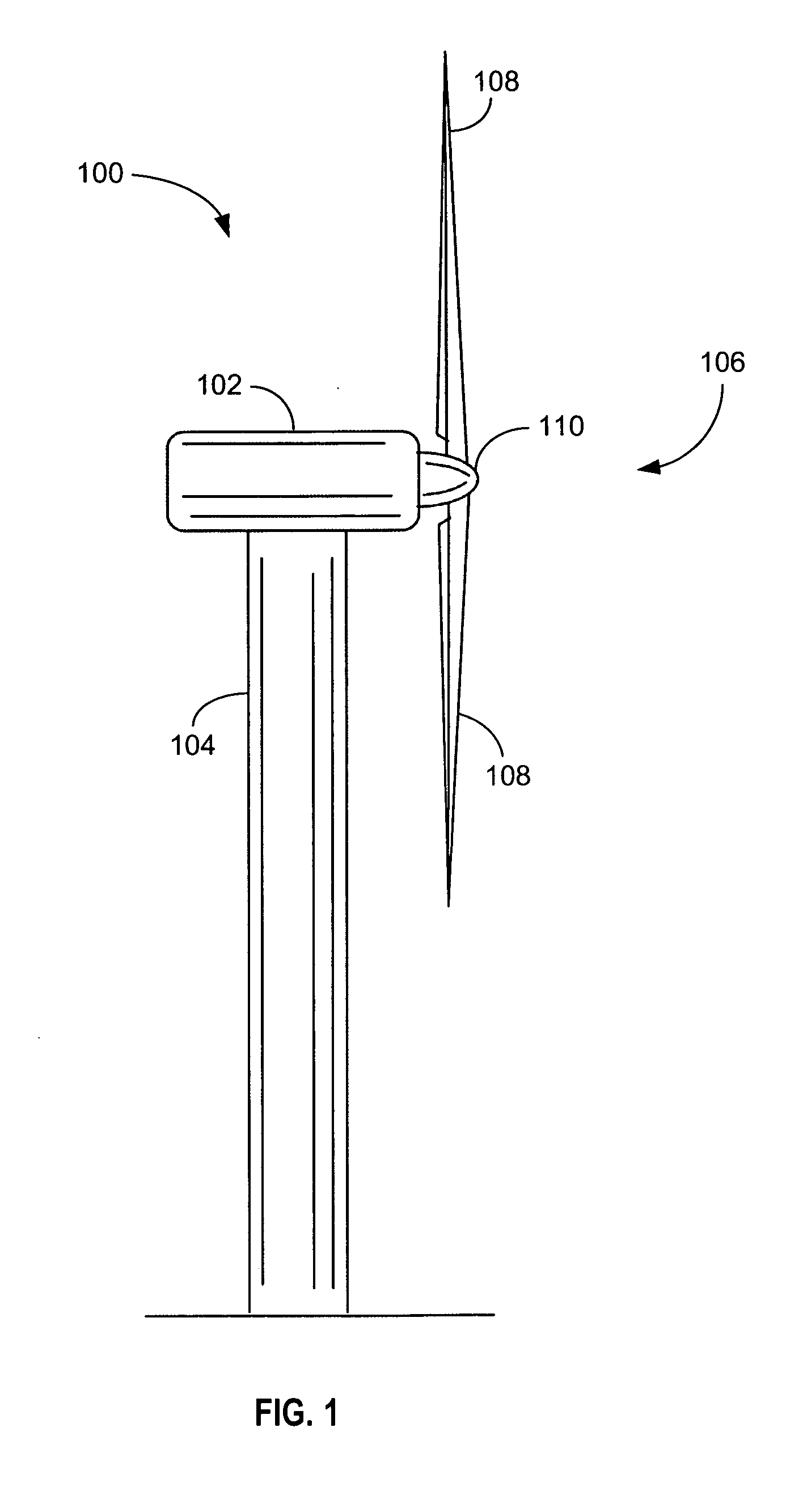
[0018]FIG. 1 is a diagram of an embodiment of a wind turbine 100 including a nacelle 102, a tower 104, a rotor 106 having at least one rotor blade 108 and a rotating hub 110. Nacelle 102 is mounted atop tower 104, a portion of which is shown in FIG. 1. Rotor blades 108 are attached to hub 110.

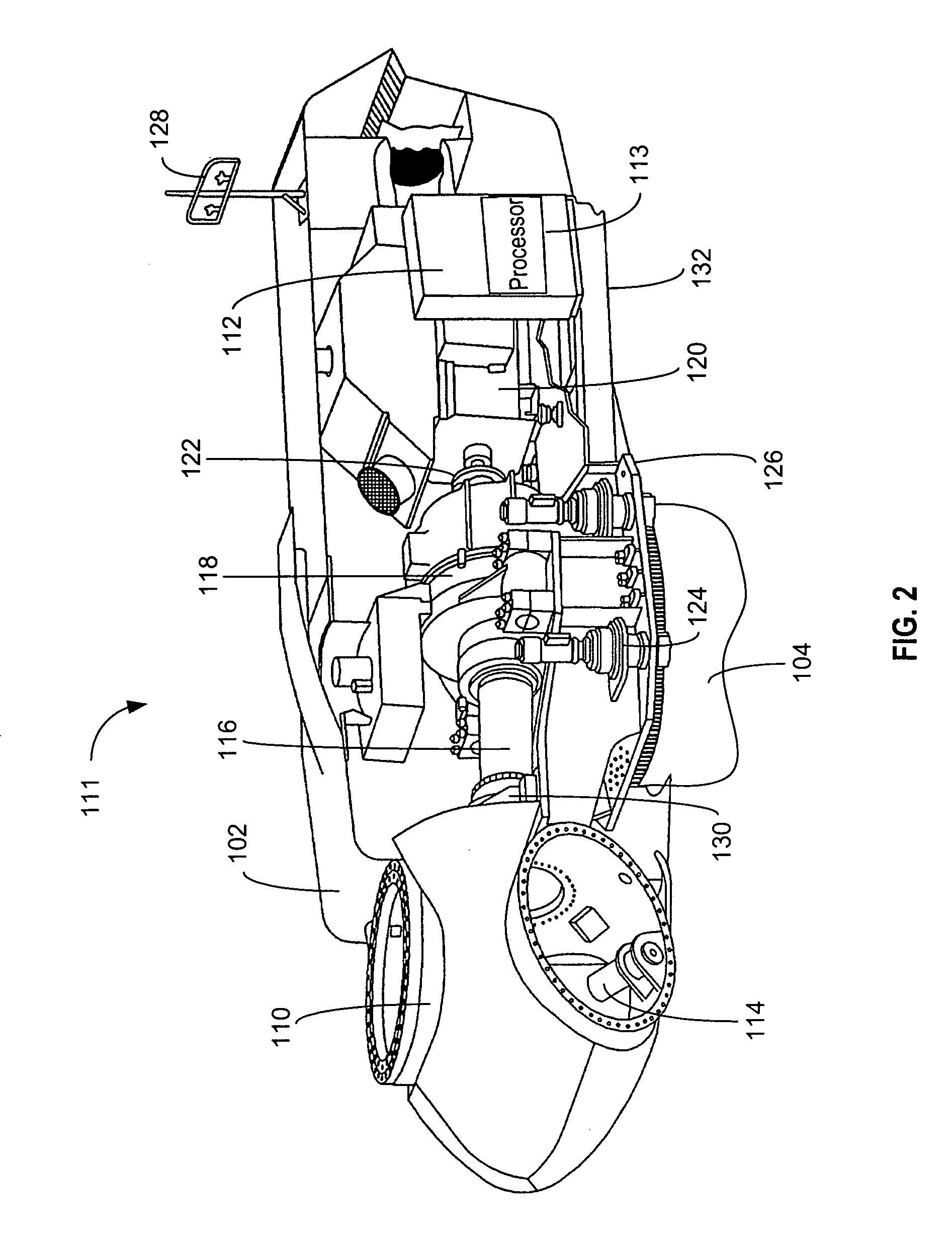
[0019]FIG. 2 is a diagram of an embodiment of a system 111 including nacelle 102, tower 104, and hub 110. Nacelle 102 houses a control panel 112 including a processor 113. As used herein, the term processor is not limited to just those integrated circuits referred to in the art as a processor, but broadly refers to a controller, a microcontroller, a microcomputer, a programmable logic controller, an application specific integrated circuit, and any other programmable circuit.

[0020] Hub 110 includes a variable blade pitch drive 114. Nacelle 102 also houses a portion of main rotor shaft 116, a gear box 118, a generator 120, and a coupling 122. A yaw drive 124 and a yaw deck 126 are housed within...


PUM


Abstract

A method for directing a current generated by a lightning striking a wind turbine is described. The method includes directing the current from a main shaft of the wind turbine to a brake disc attached to the shaft, and directing the current from the brake disc to one of a spark gap and a roller mechanism coupled to a down-conductor at a ground voltage.

Description

BACKGROUND OF THE INVENTION [0001] This invention relates generally to a wind turbine and more particularly to methods and systems for directing a current within the wind turbine. [0002] A rotor blade of a wind turbine is provided with an outer lightning down-conductor arranged on an outer surface of the blade or an inner lightning down-conductor inside the blade. The inner lightning down-conductor is provided with a lightning receptor, which is a metallic through-going connection between the inner lightning down-conductor of the blade and the outer surface of the blade. A purpose of the receptor is to attract lightning so that a lightning current generated from lightning can be guided downwards though the lightning down-conductor mounted inside the rotor blade. [0003] Use of electrically conductive material in components, such as a brake pad, a generator, and bearings supporting the generator, within the wind turbine entails a need for lightning protection or overvoltage protection...

Claims


Application Information

Patent Timeline
IPC IPC(8): F03D9/00
CPCF03D11/00F03D11/0033H02G13/00Y02E10/722Y02E10/726H02G13/80H02G13/40F03D80/00F03D80/30F03D80/70F03D15/20Y02E10/72
Inventor KRUG, FLORIANBROKFELD, STEFANTEICHMAN, RALPH
Owner GENERAL ELECTRIC CO
Why Eureka
Try Eureka