
Display panel control circuit and display device

a control circuit and display panel technology, applied in static indicating devices, non-linear optics, instruments, etc., can solve the problems of not processing external image data and sync signals, and achieve the effect of preventing image disturban

Inactive Publication Date: 2007-05-24
TOSHIBA MATSUSHITA DISPLAY TECH
View PDF4 Cites 11 Cited by
  • Summary
  • Abstract
  • Description
  • Claims
  • Application Information

AI Technical Summary

Benefits of technology

[0012] An object of the present invention is to provide a display panel control circuit and a display device, which can prevent image disturbance, which occurs immediately after supply of power.
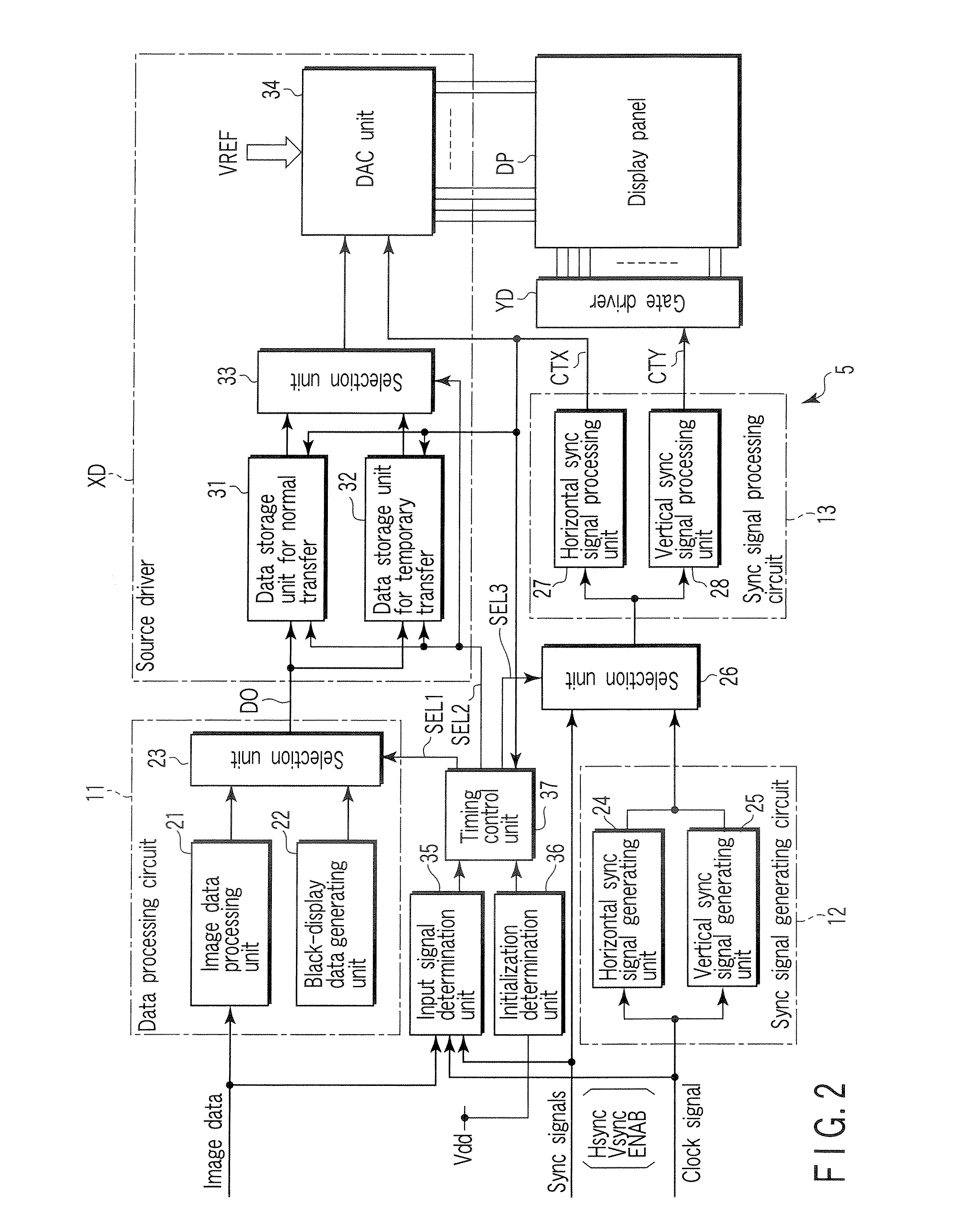
[0015] In these display panel control circuit and display device, the processing circuit provides predetermined internal image data and sync signal, which are generated immediately after supply of power and processed instead of the external image data and sync signals, and whose processing results are temporarily output to the driving circuit. Specifically, the external image data and sync signals are not in the normal state immediately after supply of power. However, the external image data and sync signals are not processed to obtain the processing results to be output to the driving circuit. Therefore, a noise-like image disturbance is prevented from occurring on the display panel.

Problems solved by technology

However, the external image data and sync signals are not processed to obtain the processing results to be output to the driving circuit.

Method used


Image

  • Display panel control circuit and display device
  • Display panel control circuit and display device
  • Display panel control circuit and display device

Examples


Embodiment Construction

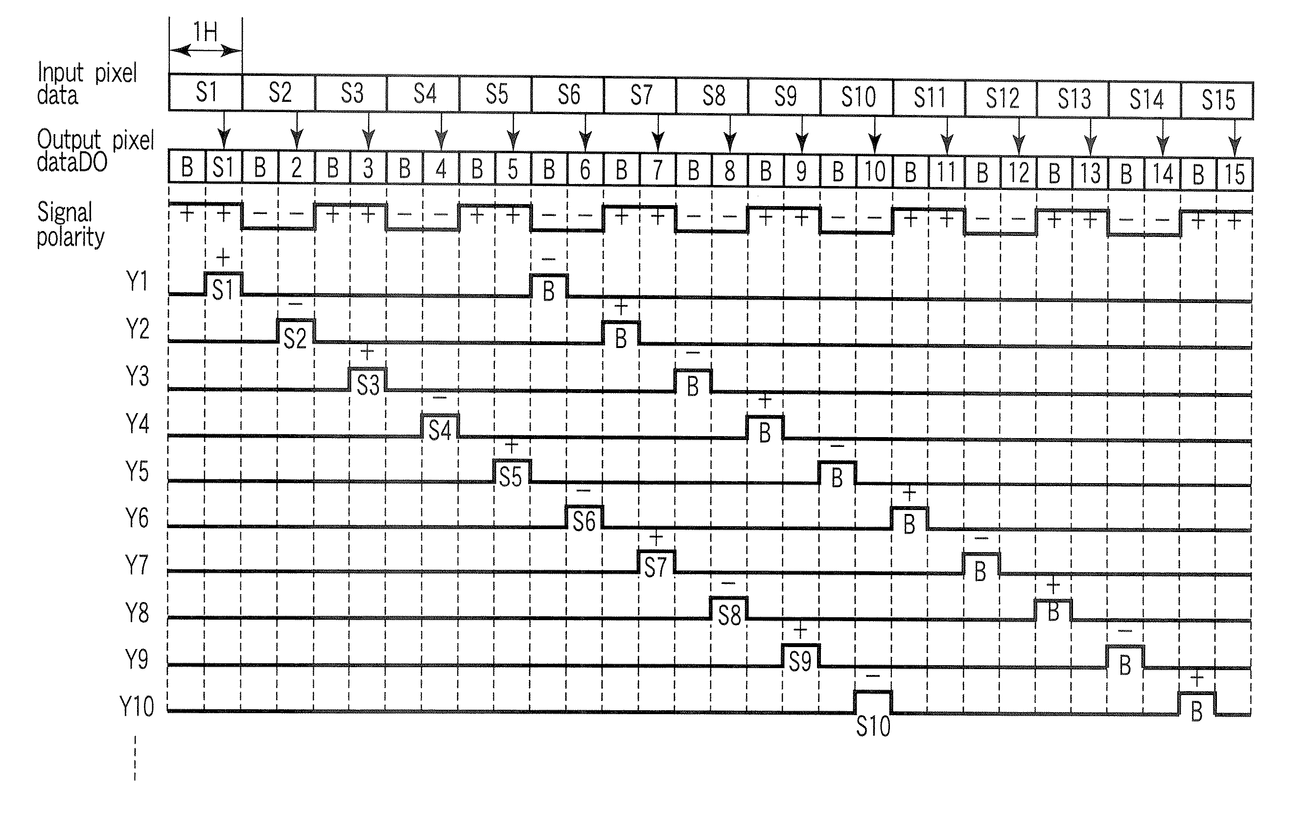
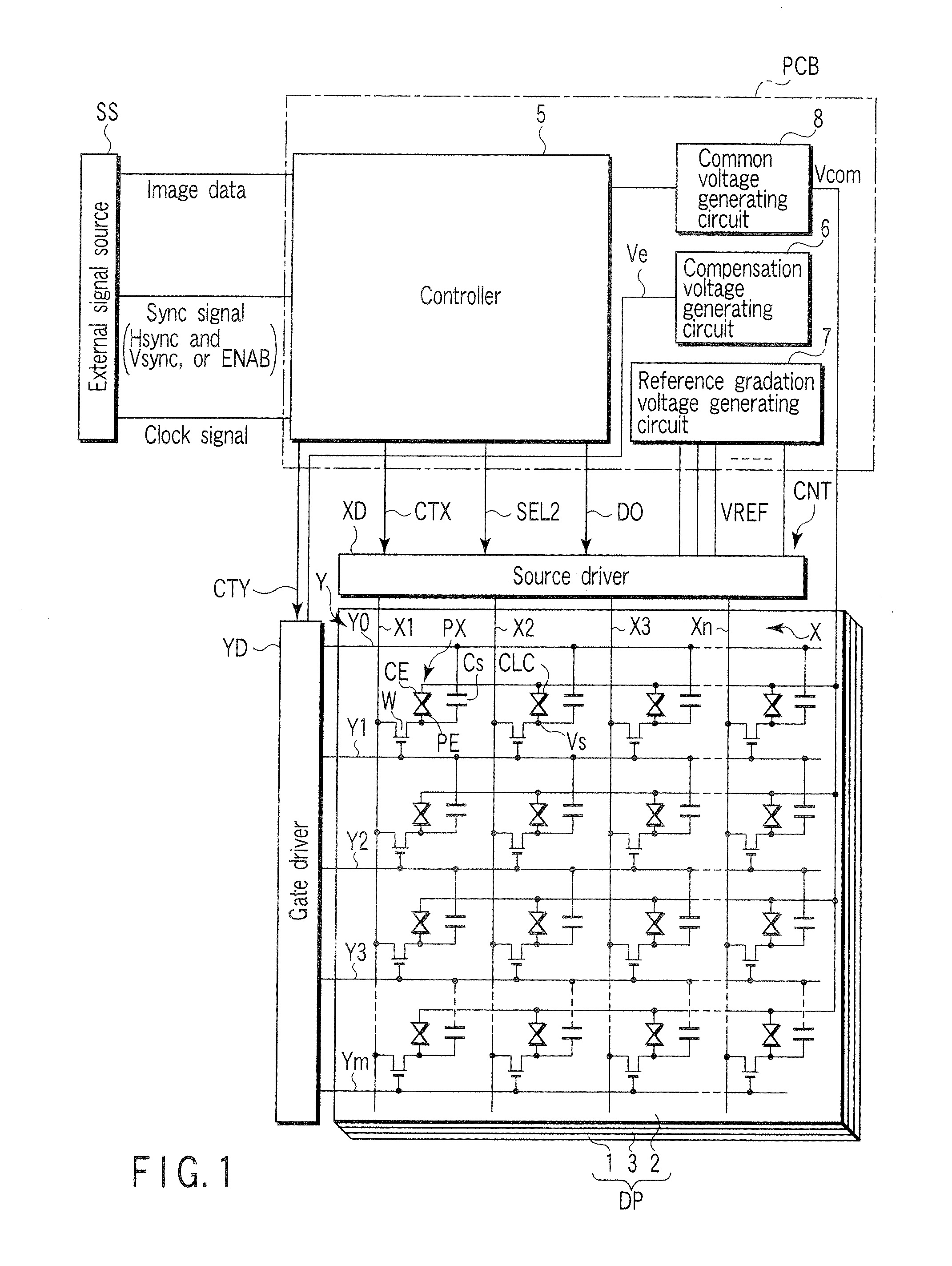
[0022] A liquid crystal display device according to an embodiment of the present invention will now be described with reference to the accompanying drawings. FIG. 1 schematically shows the circuit structure of the liquid crystal display device. The liquid crystal display device includes an OCB mode liquid crystal display panel DP, and a display panel control circuit CNT which is connected to the display panel DP. The liquid crystal display panel DP is configured such that a liquid crystal layer 3 is held between an array substrate 1 and a counter-substrate 2, which are a pair of electrode substrates. The liquid crystal layer 3 includes a liquid crystal material in which liquid crystal molecules are aligned in a splay alignment in a voltage-non-applied state. Upon supply of power, the display panel control circuit CNT performs initialization of the liquid crystal display panel DP in order to enable a normally white display operation. In the initialization, a relatively high transitio...


PUM


Abstract

A display panel control circuit includes a controller which processes external image data and sync signals from an external signal source, and source and gate drivers which drive a display panel on the basis of processed results from the controller. The controller is configured to provide predetermined internal image data and sync signals which are generated immediately after supply of power and processed instead of the external image data and sync signals, and whose processing results are temporarily output to the source and gate drivers.

Description

CROSS-REFERENCE TO RELATED APPLICATIONS [0001] This application is based upon and claims the benefit of priority from prior Japanese Patent Application No. 2005-335924, filed Nov. 21, 2005, the entire contents of which are incorporated herein by reference. BACKGROUND OF THE INVENTION [0002] 1. Field of the Invention [0003] The present invention relates to a display panel control circuit which is applied to a liquid crystal display panel of, e.g., an optically compensated bend (OCB) mode, and a display device including the display panel control circuit. [0004] 2. Description of the Related Art [0005] Flat-panel displays realized by liquid crystal display devices are widely used in computers, car navigation systems, TV receivers, and similar equipment. [0006] In general, a liquid crystal display device utilizes a liquid crystal display panel, which includes a matrix of liquid crystal pixels, and a display panel control circuit which controls this display panel. The liquid crystal disp...

Claims


Application Information

Patent Timeline
Patent Type & Authority Applications(United States)
IPC IPC(8): G09G3/36
CPCG09G3/2092G09G3/3614G09G3/3677G09G3/3688G09G2300/0491G09G2310/061G09G2320/0219G09G2330/026G02F1/133G09G3/20G09G3/36
Inventor TERANISHI, KENTARO
Owner TOSHIBA MATSUSHITA DISPLAY TECH
Learn More