Method for point-of-interest attraction in digital images

Inactive Publication Date: 2007-05-24
T2PHARMA GMBH
View PDF1 Cites 144 Cited by
  • Summary
  • Abstract
  • Description
  • Claims
  • Application Information

AI Technical Summary

Benefits of technology

[0010] The use of digital measurement templates provides a substantial means over the film-based or generic measurement methods to reduce random error by providing an unambiguous and instantaneous indication as to the position of the measurement objects in the actual image. The graphical part of the measurement template graphically shows how the measurement point relates to the anatomic outlines that appear in the medical image. However, it remains the user's responsibility to map the measurement points in the image. In musculoskeletal images, these points of interest will typically lie on the cortex of bones in the image. These cortical outlines coincide with the digital edge of the imaged bone. In 3D MR or CT images, these points typically lie on the border of organs o

Problems solved by technology

This method does not disclose however how the point mapping may be effectuated automatically without the need of user positioning and manipulation of key measurement points.
A major drawback of these prior art methods to perform geometrical measurements is increased measurement error or measurement uncertainty.
Systematic or bias errors arise from consistent and repeatable sources of error (like an offset in calibration).
Particularly this source of

Method used


Image

  • Method for point-of-interest attraction in digital images
  • Method for point-of-interest attraction in digital images
  • Method for point-of-interest attraction in digital images

Examples


Embodiment Construction

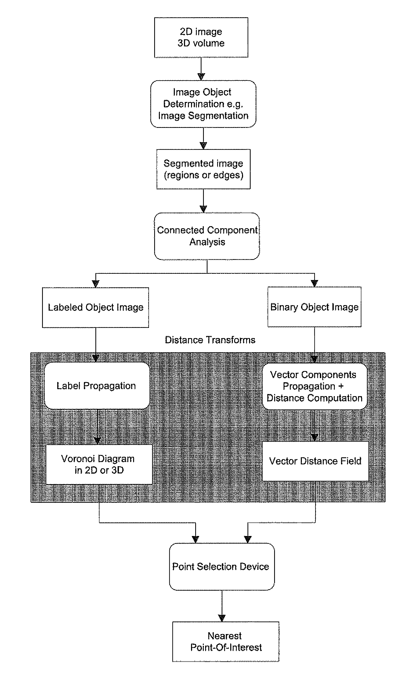
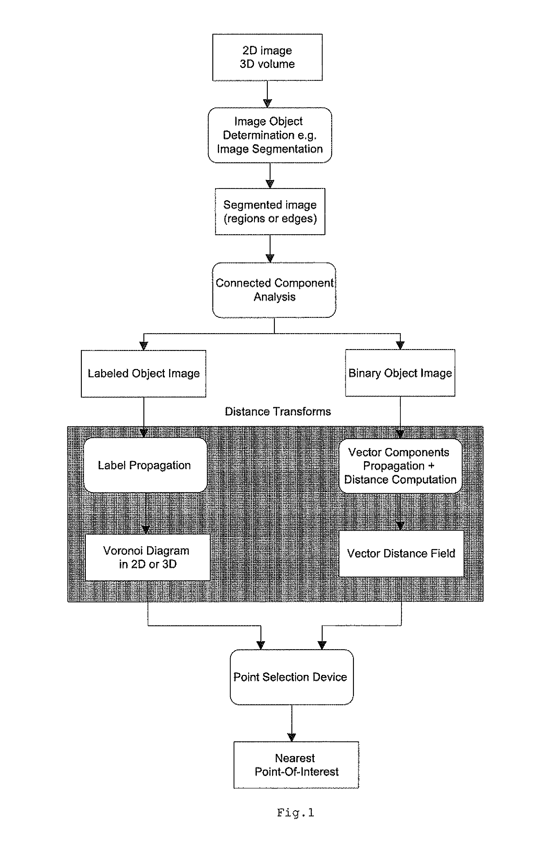
[0028] According to the present invention, a method is provided for automatic attraction of a point selection device towards a computed point of interest in the image. This point of interest belongs to an anatomic object and will usually lie on the outer border of it. The anatomic object may be represented by a contour (2D) or a surface (3D) or its dual region (2D) or volume (3D) enclosed by it. In two dimensions, the point selection device operates in the plane of the image and is characterized by its row-column position. In three dimensions, the point selection device may either operate on a slice-by-slice viewing basis, or on the 3D volume or surface visualization.

[0029] The point attraction system (FIG. 1) consists of three major building blocks. First, the object pixels are determined in the image using for example an object segmentation method. The result of this step is a separation of all pixels in the image into a class of background pixels not belonging to objects of inte...


PUM


Abstract

A method for point-of-interest attraction towards an object pixel in a digital image by first performing object segmentation resulting in a contour-based or a region-based representation of object pixels and background pixels of the image. Secondly a vector distance transform image is computed comprising a vector displacement of each background pixel towards the nearest of said object pixels and the nearest object pixel for a given background pixel is determined by adding the vector displacement to said background pixel. Finally the point-of-interest is attracted towards the determined nearest object pixel.

Description

CROSS-REFERENCE TO RELATED PATENT APPLICATIONS [0001] This application claims the benefit of U.S. Provisional Application No. 60 / 748,762 filed Dec. 8, 2005, which is incorporated by reference. In addition, this application claims the benefit of European Application No. 05111121.9 filed Nov. 23, 2005, which is also incorporated by reference.FIELD OF THE INVENTION [0002] The present invention relates to a method to automatically attract a point selection device towards a point-of-interest in the digital medical image on the basis of digital image processing. Measurements of anatomy may be based on these points-of-interest in the image. BACKGROUND OF THE INVENTION [0003] In radiological practice, geometric measurements are frequently used to diagnose abnormalities. In order to perform these measurements, key user points are placed in the image on their corresponding anatomical landmark position. Measurements such as the distance between two points, or the angulation between lines are b...

Claims


Application Information

Patent Timeline
IPC IPC(8): G06K9/34G06K9/46G06K9/00G06V10/25
CPCA61B5/1075G06K9/3233G06T7/0081G06T7/0083G06T7/0091G06T7/60G06T2207/10081G06T2207/10116G06T2207/20164G06T2207/30008G06T7/11G06T7/12G06T7/155G06V10/25
Inventor DEWAELE, PIET
Owner T2PHARMA GMBH
Why Eureka
Try Eureka