Stack-type lithium-ion polymer battery

Inactive Publication Date: 2007-05-24
NEC ENERGY DEVICES LTD
View PDF4 Cites 23 Cited by
  • Summary
  • Abstract
  • Description
  • Claims
  • Application Information

AI Technical Summary

Benefits of technology

[0017] According to the present invention, there can be provided a stack-type lithium-ion polymer battery wherein: the two or more separators and the insulating porous sheet enclosing the electrode stack are fusion-bonded and fixed to each other, so that the displacement of the electrodes can be prevented, the formation of the internal short-circuit can be prevented, the production yield can be improved, the generation of wrinkles, at the time of impregnation of the pre-gel solution or the like, during or after stacking, can be suppressed, and the formation of the internal short-circuit and the capacity degradation can be prevented; the separators and the insulating porous sheet are fusion-bonded and fixed in the peripheral portion thereof, not in contact with the electrodes, so that the gas releasing paths at the time of the impregnation of the pre-gel solution can be ensured and the capacity degradation can be prevented; the separators and the insulating porous sheet are fusion-b

Problems solved by technology

However, such a thin separator is difficult in handling, tends to undergo the displacement thereof when stacked, which may cause the formation of an internal short-circuit and the increase of the resistance due to the generation of wrinkles.
In some cases, there is adopted a structure in which a self-supported gel electrolyte sheet is used instead of using the separator; however, a short-circuit may be formed due to the decrease of the strength of the gel electrolyte when the temperature is raised, and hence the safety thereof has not been sufficient.
Also when the pre-gel solution is impregnated under a reduced pressure, the gas layer which is present in the space between the active materials is needed to be released to the outside; however, the path for releasing the gas is also limited because the support body is formed in the bag-like shape; and thus, the gas may remains.
Also when the electrode units enclosed by the porous sheet are stacked and placed in a package body, the electrodes each are independently stacked, and hence there has been a problem of poor workability.
Additionally, the separators interposed between the stacked electrodes undergo the generation of fracture due to the wrinkles or the tensile caused by the tension by the wrinkles of the outermost layer of the group of the electrodes, possib

Method used


Image

  • Stack-type lithium-ion polymer battery
  • Stack-type lithium-ion polymer battery
  • Stack-type lithium-ion polymer battery

Examples


example 1

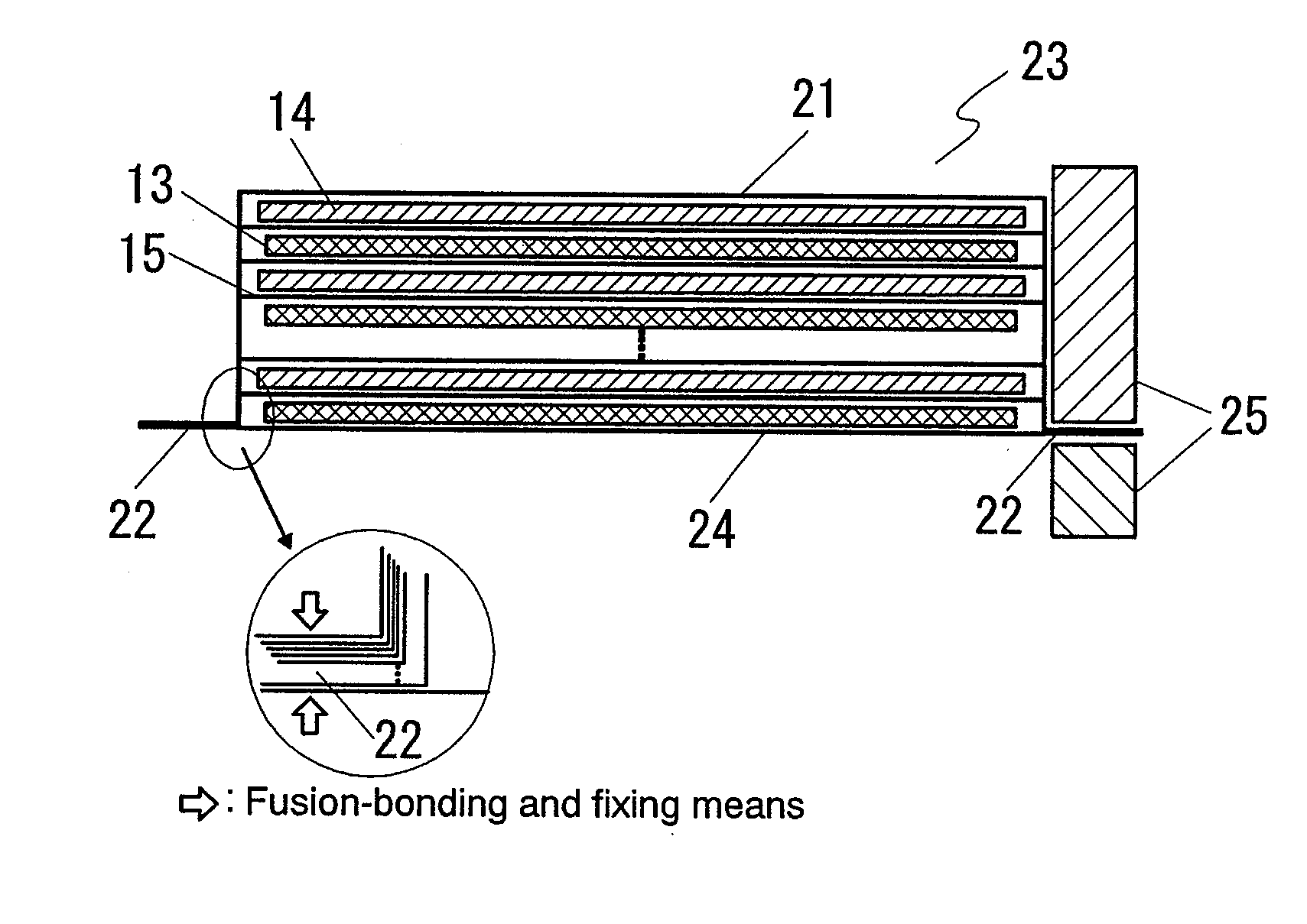
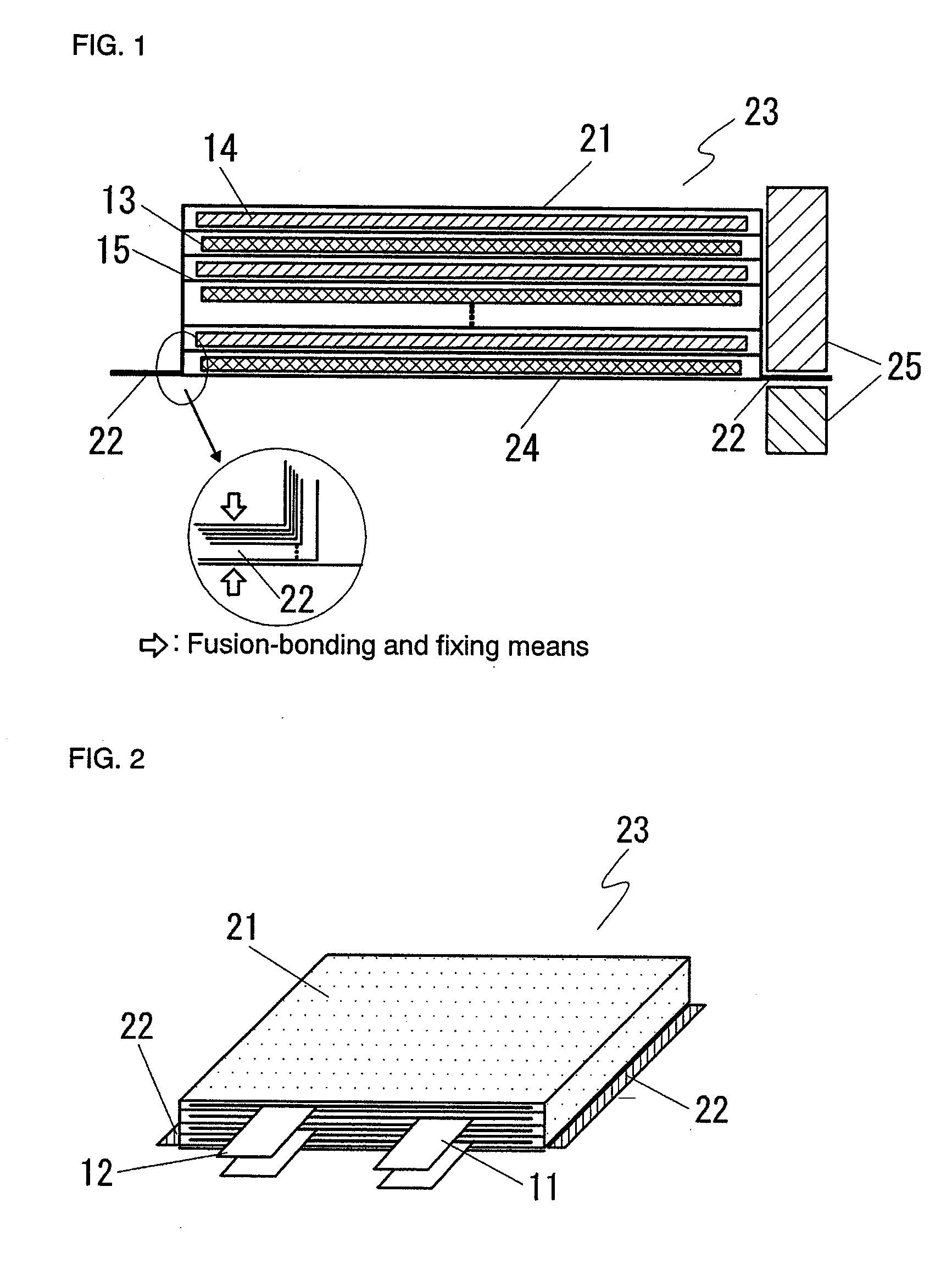
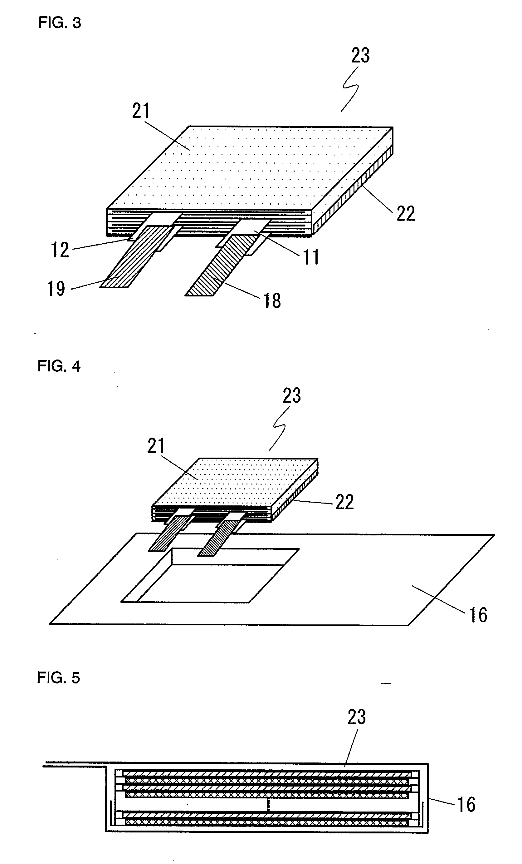
[0048] Example 1 will be described with reference to FIGS. 1 to 5. FIG. 1 is a sectional view illustrating the state when insulating porous sheets enclosing the electrode stack are being fusion-bonded and fixed in Example 1 of the stack-type lithium-ion polymer battery of the present invention; FIG. 2 is an oblique perspective view illustrating the state after fusion-bonding and fixing the insulating porous sheets illustrated in FIG. 1; FIG. 3 is an oblique perspective view illustrating the state after bending the fusion-bonded portions of the insulating porous sheets illustrated in FIG. 2; FIG. 4 is an oblique perspective view illustrating the state when the electrode stack illustrated in FIG. 3 is being placed into the laminate package body; and FIG. 5 is a sectional view illustrating the state after packaged with the laminate material in Example 1 of the stack-type lithium-ion polymer battery of the present invention.

[0049] A cathode 13 was fabricated as follows. First, a mixtur...

example 2

[0061]FIG. 6 is a sectional view illustrating the state when insulating porous sheets enclosing the electrode stack are being fusion-bonded and fixed in Example 2 of the stack-type lithium-ion polymer battery of the present invention, and FIG. 7 is an oblique perspective view illustrating the state after fusion-bonding, fixing and bending the insulating porous sheets illustrated in FIG. 6.

[0062] The insulating porous sheet 24, which had been cut to 100 mm×170 mm so as to be larger than the coated area of the anode, was placed on a concave mold 26 set at a width of 75 mm so as to be larger than the anode width of 73 mm; the cathode 13, the separator 15, the anode 14 and additionally the separator 15 were sequentially stacked in this order so as to form 10 pairs of the cathodes and the anodes. In this case, the insulating porous sheet located on the uppermost surface corresponds to the insulating porous sheet 21 on the upper end surface of the electrode stack 23. Then, a portion, whi...

example 3

[0065]FIG. 8 is an oblique perspective view illustrating the state when the electrode stack is being placed into the laminate package body in Example 3 of the stack-type lithium-ion polymer battery of the present invention, and FIG. 9 is a sectional view illustrating the state after placing the electrode stack illustrated in FIG. 8 into the laminate package body.

[0066] In this Example, the electrode stack 23 was fabricated in the same manner as in Example 1, the electrode stack was sandwiched from above and below by non-embossed flat-plate-like laminate package bodies 17 as shown in FIG. 8, and the portion thereof other than the liquid injection portion was thermally fusion-bonded as shown in FIG. 9. Except the above, the stack-type lithium-ion polymer battery was obtained as described in Example 1.


PUM

PropertyMeasurementUnit
Thicknessaaaaaaaaaa

Abstract

The present invention provides a stack-type lithium-ion polymer battery wherein: the battery capacity is not being degraded; the generation of the wrinkles and fracture of the separator is being suppressed; the battery has gas releasing paths; the displacement of an electrode stack hardly occurs; and the workability at the time of placing the electrode stack in a package body is improved by fixing the electrode stack. A stack-type lithium-ion polymer battery of the present invention comprises: a cathode 13; an anode 14; a separator 15; and a gel electrolyte; wherein an electrode stack 23 in which the cathode 13 and the anode 14 are stacked through the separator 15 is enclosed and fixed by insulating porous sheets 21 and 24, and is packaged with a laminate material.

Description

BACKGROUND OF THE INVENTION [0001] 1. Field of the Invention [0002] The present invention relates to a stack-type lithium-ion polymer battery and, more particularly, to a stack-type lithium-ion polymer battery packaged with a laminate material. [0003] 2. Description of the Related Art [0004] Because a lithium-ion polymer battery has an improved resistance to liquid leakage owing to nonuse of any electrolyte, a laminate package body which affords satisfactory productivity can be used and the battery packaged with a laminate material is characterized by having a high degree of freedom in selecting the shape thereof. [0005] At present, prismatic lithium-ion polymer batteries, packaged with a laminate material, include a wound-type battery in which wound electrodes are formed into a flat shape and a stack-type battery in which flat plate electrodes are stacked. [0006] In the stack-type battery, a cathode, a separator and an anode are sequentially stacked in this order to fabricate an el...

Claims


Application Information

Patent Timeline
IPC IPC(8): H01M2/02H01M2/08H01M10/05H01M10/052H01M10/0565H01M10/058H01M10/0585H01M50/414
CPCH01M2/1653H01M10/0525H01M10/0565Y10T29/4911Y02E60/122Y10T156/1002Y10T156/10H01M10/0585Y02E60/10Y02P70/50H01M50/414
Inventor KANEKO, SHINAKOKASAHARA, RYUICHIKOBAYASHIKONO, YASUTAKANISHIYAMA, TOSHIHIKO
Owner NEC ENERGY DEVICES LTD
Why Eureka
Try Eureka