Hydraulic controlling apparatus for automatic transmission for vehicle
- Summary
- Abstract
- Description
- Claims
- Application Information
AI Technical Summary
Benefits of technology
Problems solved by technology
Method used
Image
Examples
Embodiment Construction
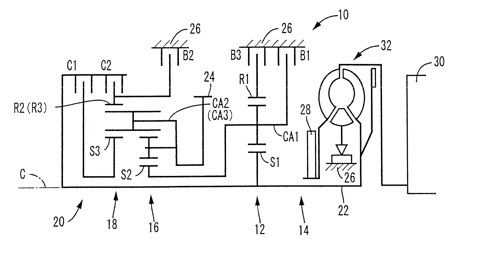
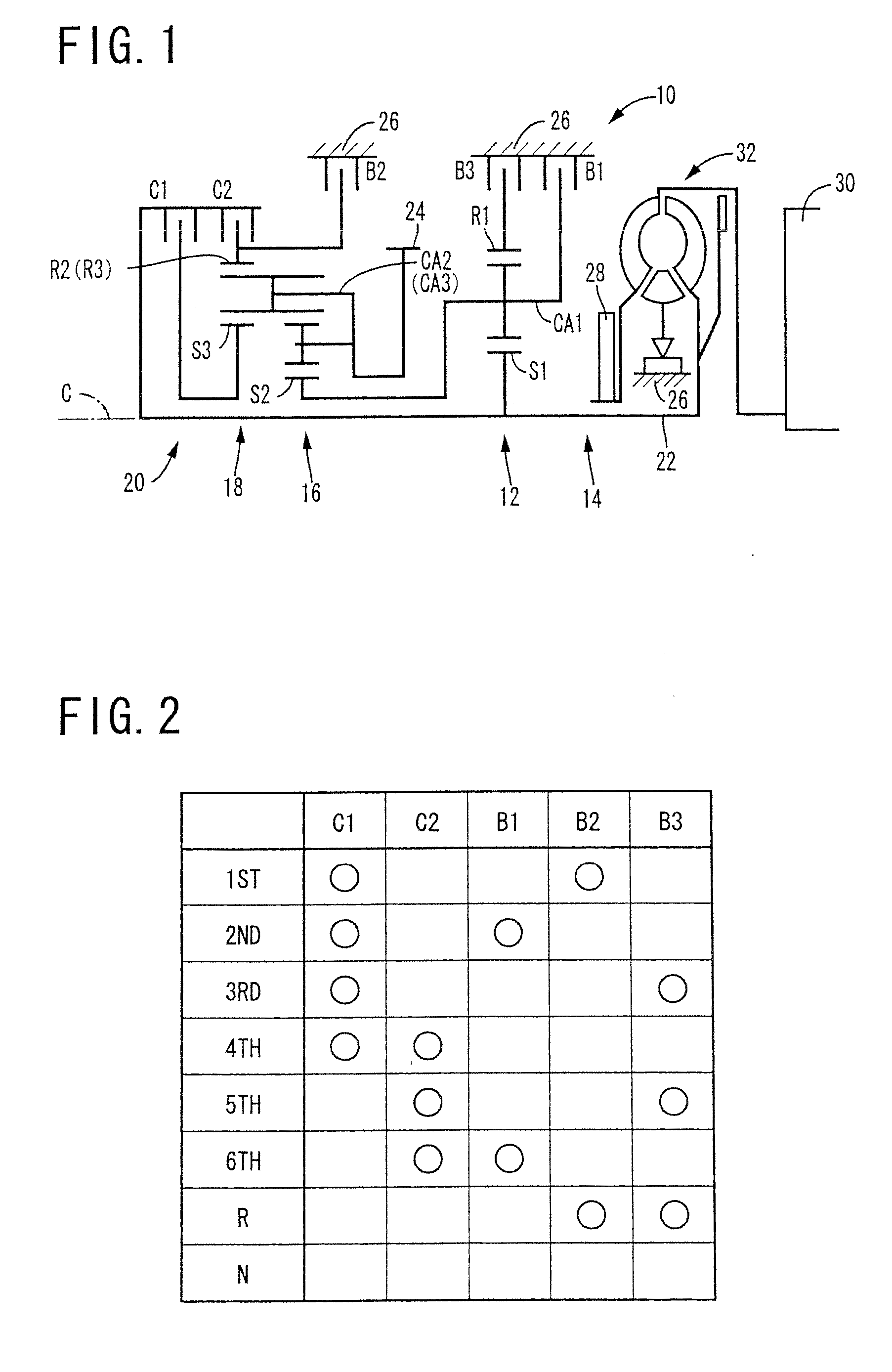
[0041] In the following, an embodiment of the present invention will be explained with reference to attached drawing. FIG. 1 is a framework view explaining structure of an automatic transmission for vehicle (hereinafter briefly referred to an “automatic transmission”) 10 to which the present invention is applied, and FIG. 2 is an operation table explaining frictionally engaging elements i.e., frictionally engaging devices for establishing plural speed-change steps. This transmission 10 is preferably mounted on a front engine, front drive type vehicle in a lateral direction i.e., right-left direction. In a transmission casing 26 as a non-rotatable member to be fixed to a vehicle body, a first speed-change part 14 and a second speed-change part 20 are mounted on a common shaft having a common axis C. The first speed-change part 14 is mainly comprised of a first planetary gear unit 12 of single pinion type, while the second speed-change part 20 has a predetermined type which is mainly ...
PUM
 Abstract
Description
Claims
Application Information
 - R&D
- Intellectual Property
- Life Sciences
- Materials
- Tech Scout
- Unparalleled Data Quality
- Higher Quality Content
- 60% Fewer Hallucinations
Browse by: Latest US Patents, China's latest patents, Technical Efficacy Thesaurus, Application Domain, Technology Topic, Popular Technical Reports.
© 2025 PatSnap. All rights reserved.Legal|Privacy policy|Modern Slavery Act Transparency Statement|Sitemap|About US| Contact US: help@patsnap.com


