Filter rod making machine

a filter rod and machine technology, applied in tobacco smoke filters, food science, tobacco, etc., can solve the problems of difficult to increase the speed of forming the composite element column, and difficult to increase the traveling speed of the composite element rod as desired

Inactive Publication Date: 2007-05-24
JAPAN TOBACCO INC
View PDF3 Cites 48 Cited by
  • Summary
  • Abstract
  • Description
  • Claims
  • Application Information

AI Technical Summary

Benefits of technology

[0008] The primary object of this invention is to provide a filter rod making machine capable of adjusting the cutt...

Problems solved by technology

However, since the composite element column is formed by arranging different types of filter elements alternately on the conveyor as mentioned above, it is diffic...

Method used


Image

  • Filter rod making machine
  • Filter rod making machine
  • Filter rod making machine

Examples


Embodiment Construction

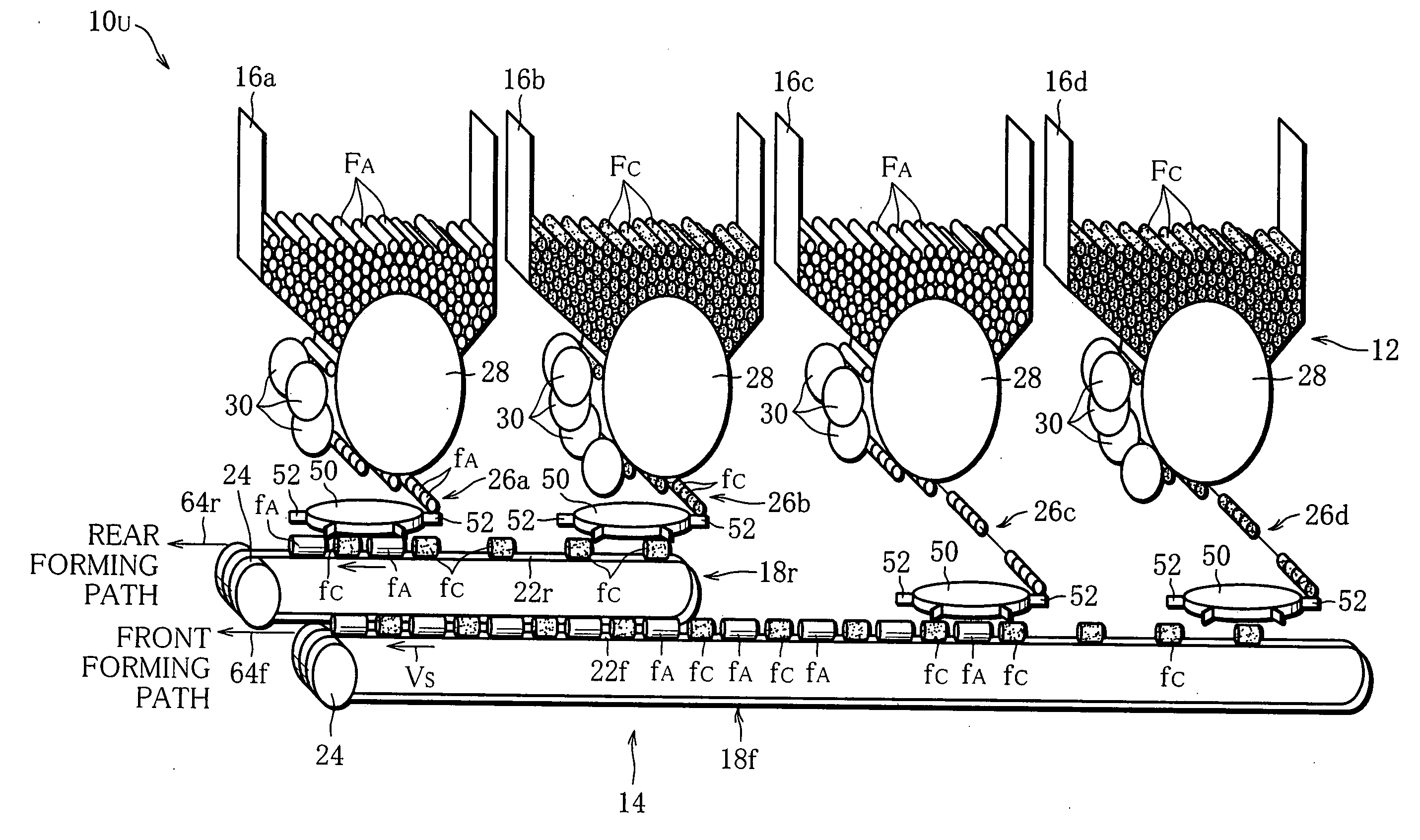
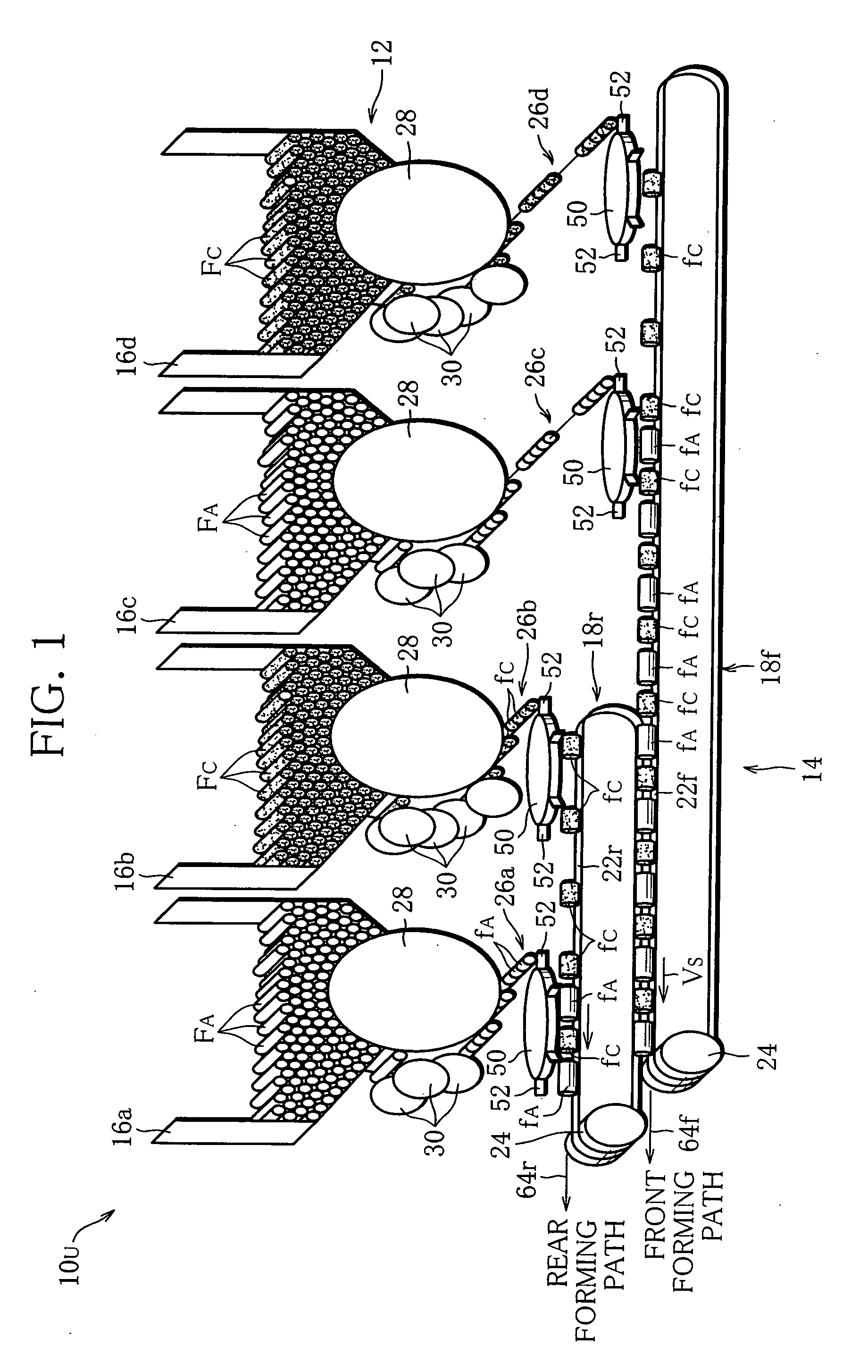
[0039]FIG. 1 shows an upstream section 10U of a double-track-type filter-rod making machine.

[0040] The upstream section 10U includes a hopper apparatus 12, and the hopper apparatus 12 comprises, for example four hoppers 16a to 16d. These hoppers 16 are arranged horizontally adjacent to each other and each store a large number of departing rods. Specifically, in FIG. 1, in the first and third hoppers 16a and 16c from the left are stored plain rods FA as departing rods, while in the hoppers 16b, 16d, charcoal rods FC different from the plain rods FA are stored as departing rods.

[0041] The plain rod FA includes a bundle of acetate fiber and wrapping paper which is wrapped around the fiber bundle to form it into a rod-like shape. The charcoal rod FC is obtained by including activated charcoal particles in the plain rod, where the activated charcoal particles are uniformly distributed in the fiber bundle.

[0042] The upstream section 10U further includes a front conveyor 18f and a rear ...


PUM


Abstract

A filter rod making machine comprises a plurality of feed wheels (50) for feeding filter elements (fA, fC) at intervals; a conveyor (18) for receiving the filter elements (fA, fC) from the feed wheels (50) and forming an element stream in which the filter elements (fA) and the filter element (fC) are arranged alternately; a wrapping apparatus (62) for forming the element stream into a composite element column (CE) in which the filter elements (fA, fC) are in close contact with each other, and then into a composite element rod (ER) by wrapping the composite element column (CE) in a paper web (W); a cutting apparatus (92) for cutting the composite element rod (ER) into individual filter rods (FR); and a phase change apparatus (112) for adjusting the rotation phase of the feed wheel (50) on the basis of information on the filter rod (FR) cut.

Description

TECHNICAL FIELD [0001] This invention relates to a machine for making a filter rod which is a connected series of composite filters such as dual filters, for manufacturing filter cigarettes, and particularly a machine with double tracks for making filter rods. BACKGROUND ART [0002] A machine for making this type of filter rod is disclosed in Japanese Unexamined Patent Publication No. 2003-24035, for example. The making machine in this publication includes a conveyor for cylindrical filter elements, and two types of filter elements are fed onto the conveyor. The two types of filter elements are arranged alternately on the conveyor, along the direction of conveyor transportation, and transported in one direction by the conveyor. In the terminal region of the conveyor, adjacent filter elements come into close contact, thereby forming a composite element column, and the formed composite element column is fed from the conveyor to a wrapping apparatus. The wrapping apparatus wraps the com...

Claims


Application Information

Patent Timeline
IPC IPC(8): B31C13/00B31C99/00
CPCA24D3/0254A24D3/0287A24D3/0295
Inventor KUSHIHASHI, SHIGENOBUSAITO, MASAYOSHIISHII, SHINJI
Owner JAPAN TOBACCO INC
Why Eureka
Try Eureka