Anatomical cavity implant transport device and method

a technology of anatomical cavity and transport device, which is applied in the field of anatomical cavity implant transport device, can solve the problems of difficult to insert a device without losing substantial body fluid, the device being inserted is exposed to excessive trauma during insertion, and the device being inserted is difficult to facilitate the placement of a non-compressible prosthetic valve through the wall, etc., to achieve safe and reliable insertion of relatively large devices, without significant blood loss, and without damage to the fragile device

Inactive Publication Date: 2007-05-24
POKORNEY JAMES L
View PDF11 Cites 93 Cited by
  • Summary
  • Abstract
  • Description
  • Claims
  • Application Information

AI Technical Summary

Problems solved by technology

Unfortunately, due to design and manufacturing comprises required to compress this type of valve, the valve performance is considered sub-optimal to those knowledgeable in the art compared to non-compressible, currently used prosthetic valves.
Currently, there are no devices to facilitate the placement of a non-compressible prosthetic valve through the wall of left ventricle without losing excessive blood or without applying excessive trauma to the valve implant.
A valve design such as that described in U.S. Pat. Nos. 7,081,089; 5,350,364; and 6,582,364 B2 may also be considered to insert a large device into an anatomical cavity without causing excessive trauma, but because these designs have only one sealing element, it would be very difficult to insert a device without loosing substantial body fluid.
Valve designs described by U.S. Pat. Nos. 5,041,095 and 5,782,817 represent a design style that could limit fluid loss, but because of the tight seals required to achieve this goal, the device being inserted is exposed to excessive trauma during insertion.
To those knowledgeable in medical device design, this type of design would not be useful to insert a large device such as a prosthetic heart valve.

Method used


Image

  • Anatomical cavity implant transport device and method
  • Anatomical cavity implant transport device and method
  • Anatomical cavity implant transport device and method

Examples


Embodiment Construction

Structure

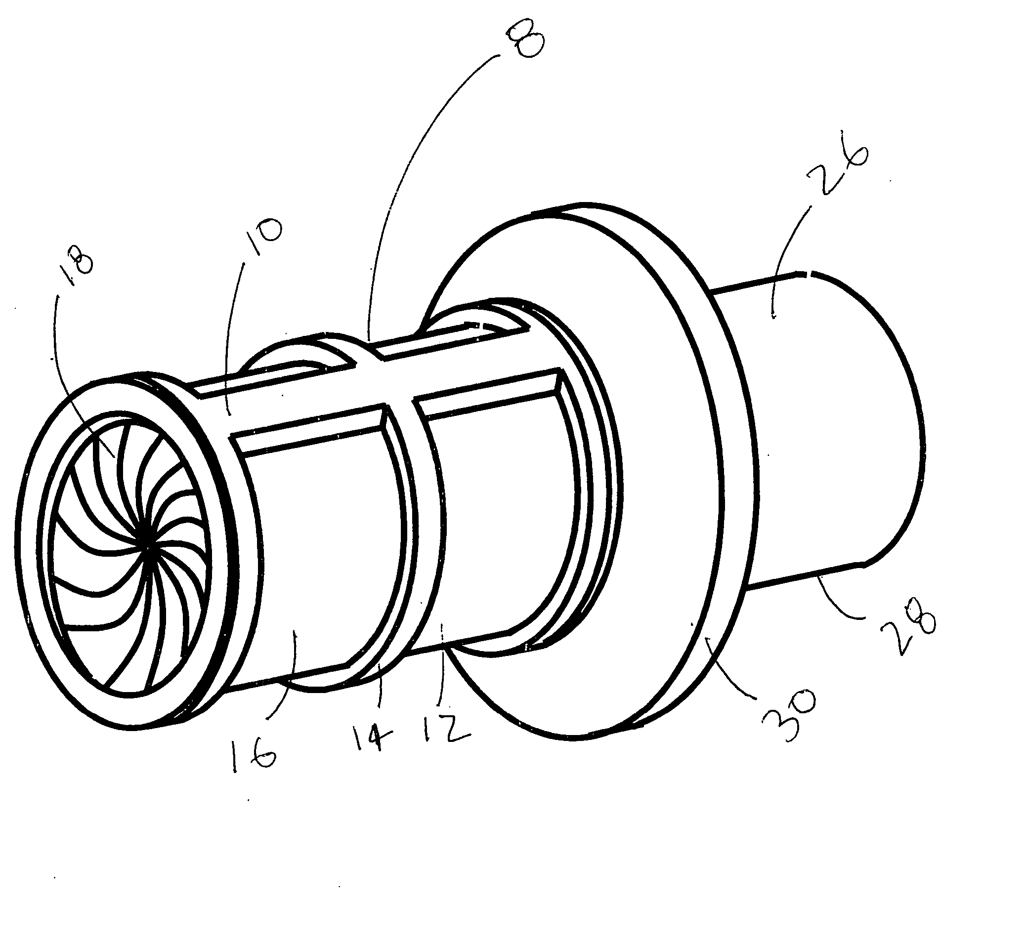
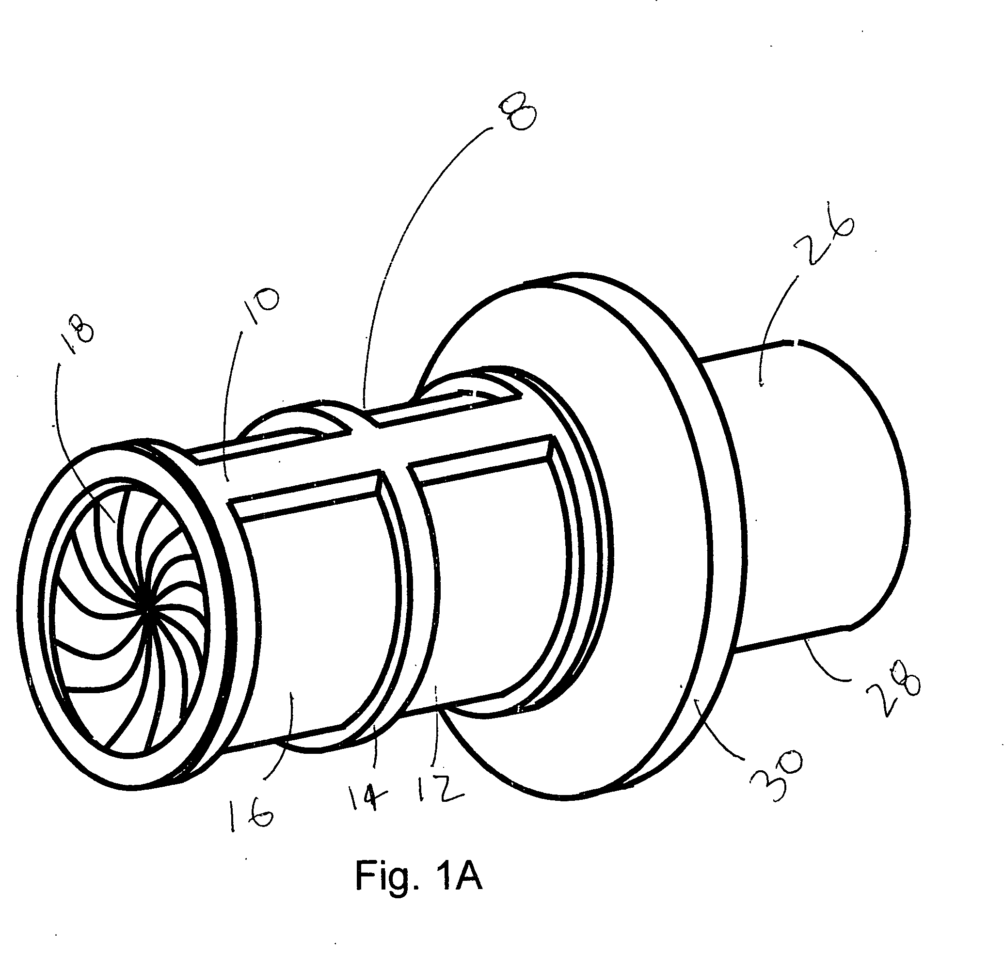
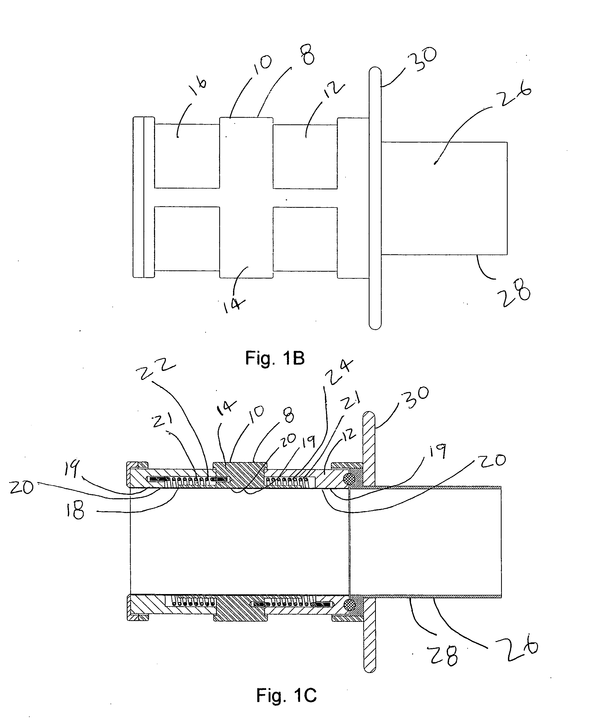
[0039] A preferred embodiment of the Anatomical Cavity Implant Transport Device 8 is shown in FIGS. 1A, 1B, and 1C. The Device 8 is comprised of the following elements: a Cylindrical Element 10, an Elastomeric Tubular Element 18, an Attachment Means 19 to connect the Elastomeric Tubular Element 18 to the Cylindrical Element 10 at three locations, Rotational Means 21 to selectively bias the Elastomeric Tubular Element 18 into a twisted, closed configuration at two locations.

[0040] This embodiment can be further described. The Cylindrical Element 10 is comprised of a three independent components; a Distal Housing 12, a Cargo Housing 14, and a Proximal Housing 16. These housings are composed of suitable rigid biomedical materials such as a plastic, like polycarbonate or polyester, or a metal such as stainless steel. A Cylindrical Elastomeric Member 18 is located adjacent to and coaxial to the Cylindrical Element 10. The Elastomeric Member 18 is composed of latex, silicone, po...


PUM


Abstract

This invention describes a device and method for inserting a large diameter object into a blood filled, pressurized cavity in the body without applying undue trauma to the object as it passes through the device and without loosing significant amounts of blood. The invention comprises the following elements: three rigid hollow cylindrical elements aligned along a common axis, an elastomeric tubular element located within the housings, attachment means to connect the elastomeric tubular element to the three rigid hollow cylindrical elements, independent rotational means such as torsion springs to selectively bias the elastomeric tubular element into a twisted, closed configuration at each boundary between the three rigid hollow cylindrical elements, and a cavity access element to gain access into the anatomical cavity.

Description

[0001] This application claims priority from provisional patent application U.S. Ser. No. 60 / 739,359 filed 2005 Nov. 22.BACKGROUND—FIELD OF INVENTION [0002] This invention relates to an anatomical cavity implant transport device and associated method to insert relatively large implants or tools into a body cavity without loosing a significant amount of fluid contained within the cavity and without damaging the device during the insertion procedure. More specifically, this invention relates to a double valved device that allows the direct insertion of a large diameter heart valve prosthesis through the wall of a beating heart without significant blood loss or damage to the fragile valve. BACKGROUND—CLINICAL NEED [0003] In many clinical applications, a doctor would like to insert a large implant or tool into a body cavity without loosing excessive fluid and without damaging the implant or tool during the insertion process. A good example of such an application is the insertion of a re...

Claims


Application Information

Patent Timeline
Patent Type & Authority Applications(United States)
IPC IPC(8): A61F2/24A61B1/32
CPCA61B17/3421A61B17/3423A61B17/3462A61B17/3496A61B17/3498A61B2017/3482A61F2/24A61B2017/3425
Inventor POKORNEY, JAMES L.
Owner POKORNEY JAMES L
Why Eureka
Try Eureka