System and method for improved ablation of tumors

a tumor and ablation technology, applied in the field of tumor ablation, can solve the problems of difficult to precisely define the location and contour of the detected structure, the resolution of pet data may not be particularly high, and the repetition is painful, so as to achieve the effect of improving the ablation

Inactive Publication Date: 2007-05-24
GENERAL ELECTRIC CO
View PDF5 Cites 17 Cited by
  • Summary
  • Abstract
  • Description
  • Claims
  • Application Information

AI Technical Summary

Benefits of technology

[0010] Certain embodiments of the present invention provide methods and systems for improved tumor ablation. Certain embodiments of a method include determining a distance between a tumor and at least one of a plurality of land

Problems solved by technology

The resolution of PET data may not be particularly high as compared to other imaging technologies, such as, for example, CT.
This low resolution makes it difficult t

Method used


Image

  • System and method for improved ablation of tumors
  • System and method for improved ablation of tumors
  • System and method for improved ablation of tumors

Examples


Embodiment Construction

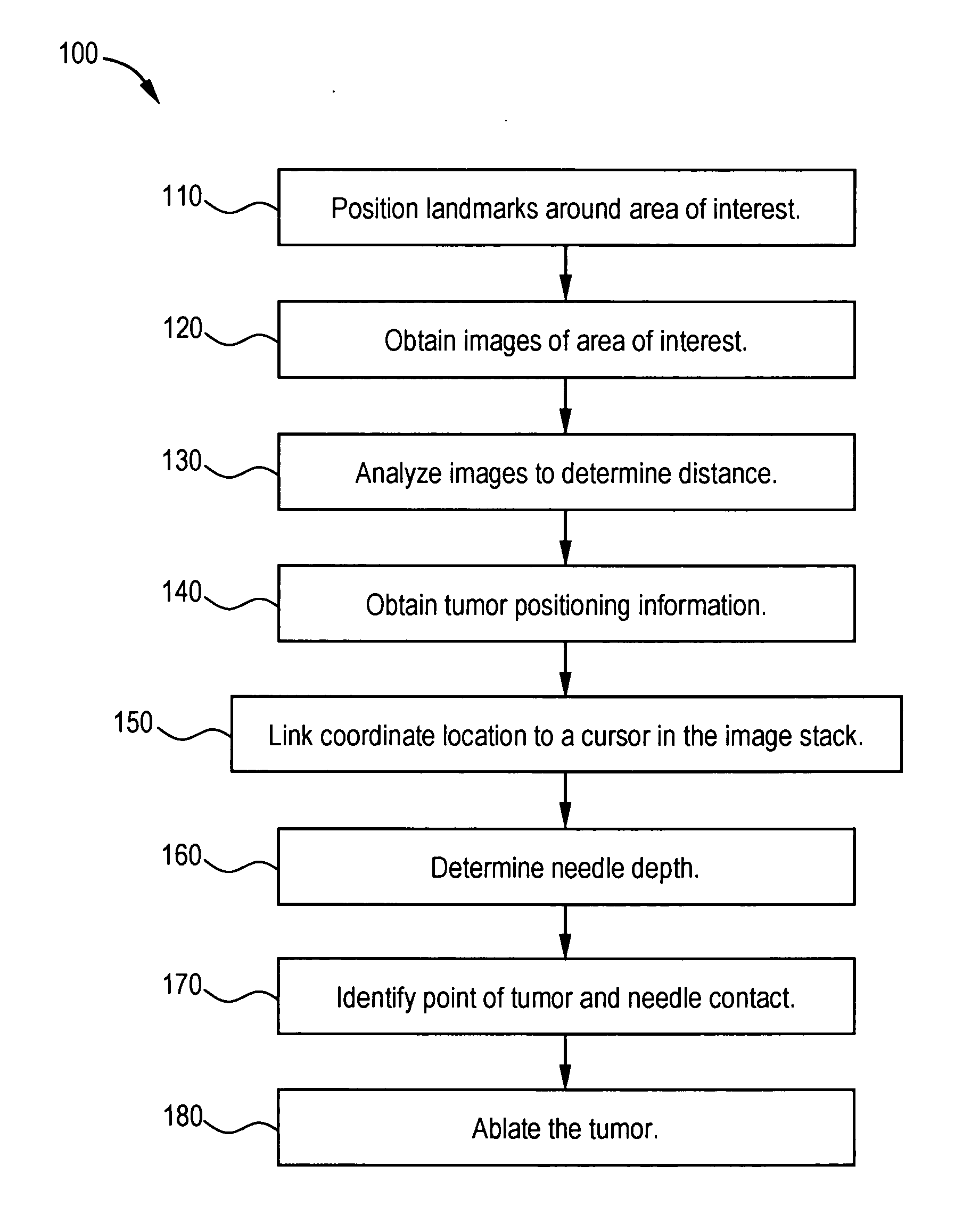
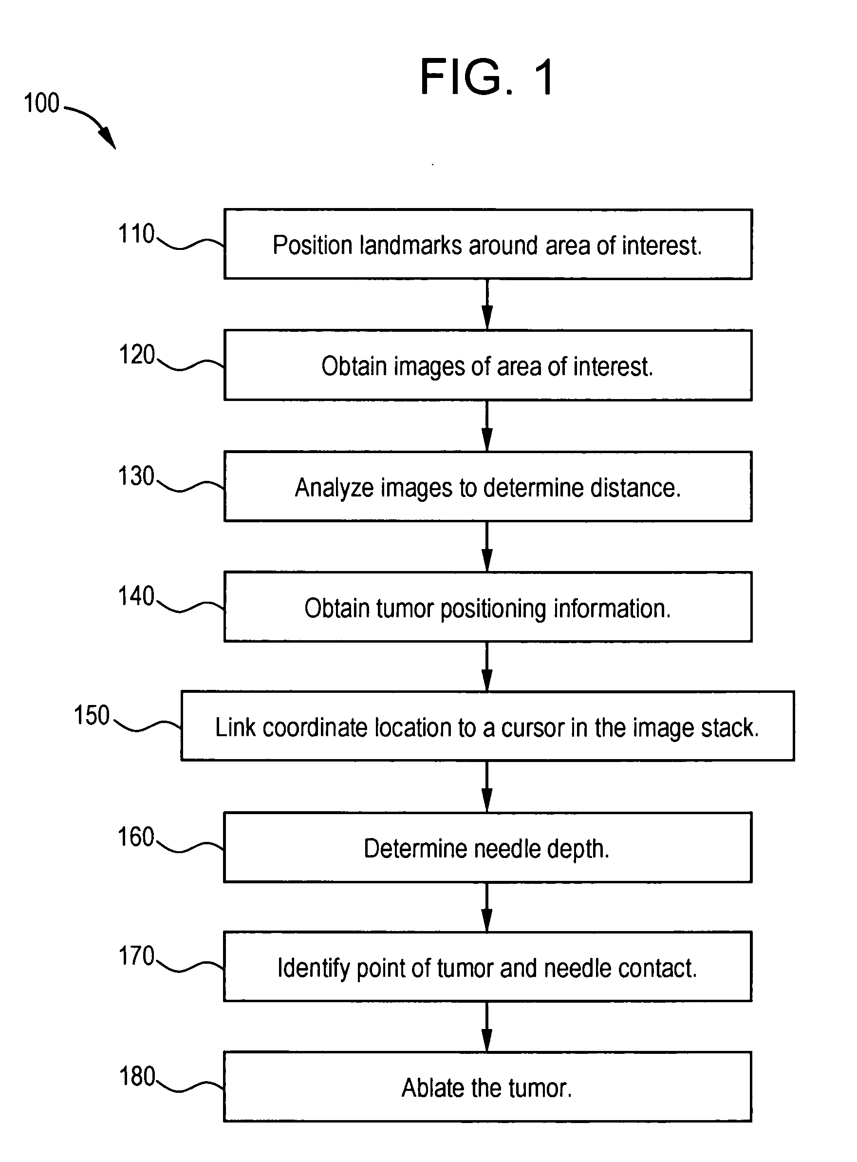
[0021]FIG. 1 illustrates a flow diagram for a method 100 for tumor ablation in accordance with an embodiment of the present invention. First, at step 110, a patient is fitted with two or more anatomical landmarks bounding an area of interest. For example, two metal rods may be placed on two sides of an area of interest including a tumor. The landmarks may be placed, taped, affixed, and / or otherwise positioned on or near the patient with respect to the area of interest. The landmarks may be chosen to appear in all axial image slices of the area of interest, for example.

[0022] At step 120, images of the area of interest are obtained. For example, a CT exam is performed without a contrast dye injection and with a contrast dye injection. The CT exam series is used to identify the guide landmarks in image slices. Then, at step 130, images are analyzed to determine one or more distance(s) between the tumor and the guide landmarks. The distance is marked or otherwise indicated on the imag...


PUM


Abstract

Certain embodiments of the present invention provide methods and systems for improved tumor ablation. Certain embodiments include determining a distance between a tumor and at least one of a plurality of landmarks bounding the tumor in at least one acquired image of an area of interest for a patient, obtaining positional data for an ablation instrument, and displaying a position of the ablation instrument with respect to the tumor. Additionally, a position of the ablation instrument may be dynamically displayed on the fluoroscopic image and/or the at least one acquired image during tumor ablation. Furthermore, a location cursor on the fluoroscopic image may be linked with a location cursor on the one or more acquired images. In certain embodiments, a location of a tip of the ablation instrument may be dynamically displayed with respect to a starting location and an ending location of the tumor.

Description

BACKGROUND OF THE INVENTION [0001] The present invention generally relates to tumor ablation. In particular, the present invention relates to systems and methods for improved ablation of tumors using a PACS. [0002] Medical imaging systems may be used to capture images to assist a physician in making an accurate diagnosis. For example, a physician may use one or more images to visually identify a tumor, lesion, and / or other anomalous structure in a patient. As another example, a physician may compare images taken over a series of patient visits to examine the evolution of a structure and / or to evaluate the effectiveness of a treatment. That is, the physician may examine morphological changes, such as changes in size and / or shape, of a tumor to evaluate its characteristics and / or the effectiveness of therapy. [0003] Image data may come from a variety of sources. Images may be generated and / or acquired from one or more imaging sessions and involve different modalities (e.g., ultrasound...

Claims


Application Information

Patent Timeline
IPC IPC(8): A61B18/18
CPCA61B18/1477A61B19/52A61B19/5244A61B2018/00577A61B2018/1425A61B2019/5238A61B2019/5289A61B2019/5483A61B34/20A61B90/36A61B2090/364A61B2090/376A61B2090/3983
Inventor MAHESH, PRAKASHMORITA, MARK M.
Owner GENERAL ELECTRIC CO
Why Eureka
Try Eureka