Method and apparatus for navigating a cutting tool during orthopedic surgery using a localization system

a surgical navigation and cutting tool technology, applied in the field of surgical navigation systems, can solve the problems of surgeons finding it difficult to accurately position the cutting tool, and achieve the effect of accurate cutting bone and extra accuracy

Inactive Publication Date: 2007-05-24
AESCULAP AG
View PDF9 Cites 22 Cited by
  • Summary
  • Abstract
  • Description
  • Claims
  • Application Information

AI Technical Summary

Benefits of technology

[0024] The present invention provides methods and apparatus that overcome the aforementioned problems by permitting one to accurately cut bone with a surgical cutting device, such as a sagittal saw, using a surgical navigation system without use of a complex cutting jig. In accordance with a first aspect of the invention, a surgical navigation system is used to navigate a guide tube that will be used to drill a k-wire into the bone. The k-wire will act as a guide to control at least one degree of freedom of a saw blade for making a cut in a bone. In an exemplary high tibial osteotomy procedure, for example, in which two intersecting planar cuts must be made in the tibia in order to remove a wedge of bone, a surgical navigation marker is mounted on the guide tube. The surgeon uses the surgical navigation system to navigate t

Problems solved by technology

However, for reasons well understood by those working in the field of knee surgery, and particularly HTO surgery, these angles might be off by a degree or two in some cases.
The surgeon typically controls the depth of the cut manually, as the cutting jig does not control cut depth.
Some surgeons find it difficult to positi

Method used


Image

  • Method and apparatus for navigating a cutting tool during orthopedic surgery using a localization system
  • Method and apparatus for navigating a cutting tool during orthopedic surgery using a localization system
  • Method and apparatus for navigating a cutting tool during orthopedic surgery using a localization system

Examples


Embodiment Construction

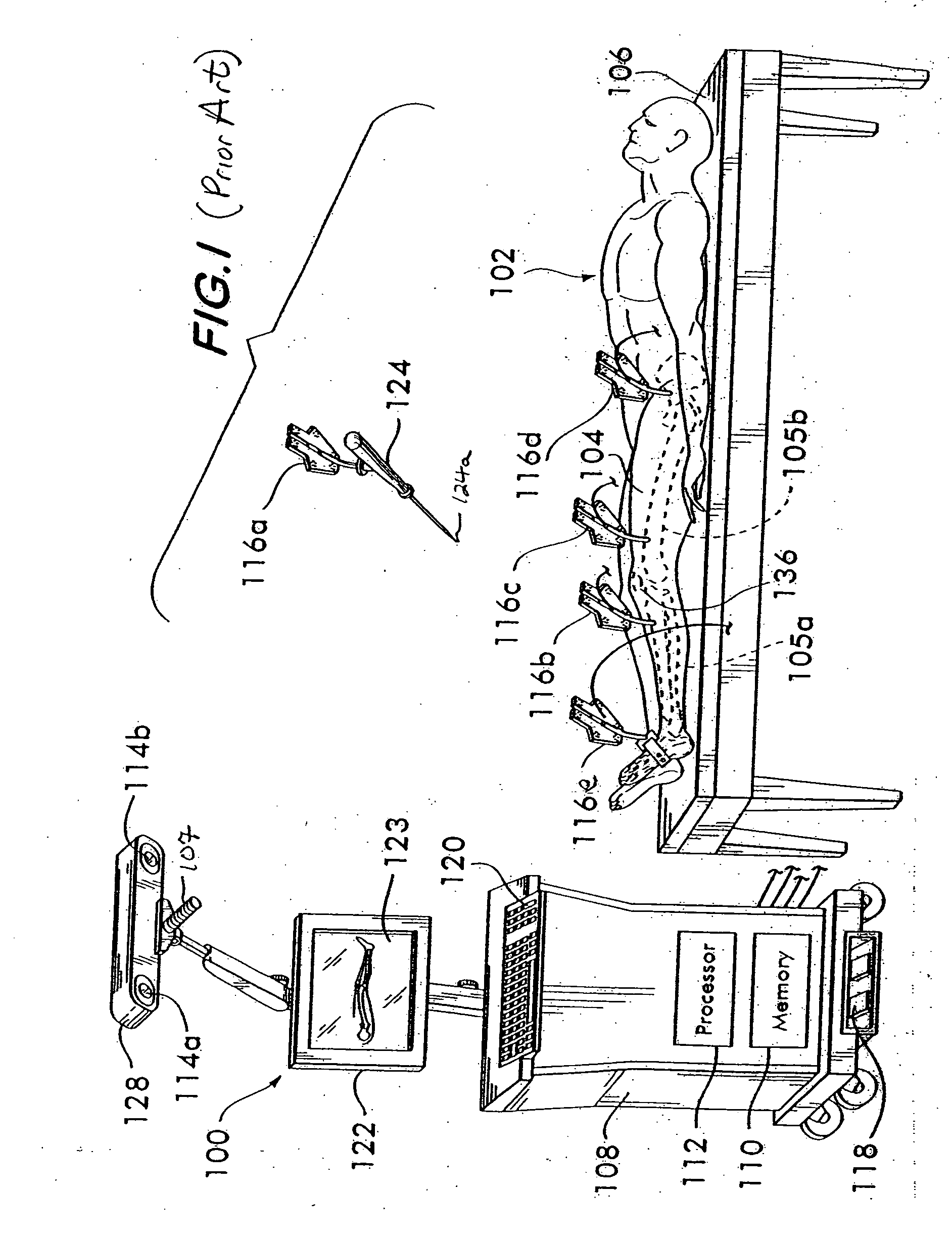
[0035] A description of a suitable localization device for use in connection with the present invention is found in U.S. Pat. No. 6,385,475 to Cinquin et al., incorporated herein by reference.

[0036] The present invention will be described in connection with an exemplary high tibial osteotomy (HTO) surgical procedure. However, it should be understood that the invention has broader applications and can essentially be applied to any bone cutting. As will become apparent from the discussion below, the technique in accordance with the present invention is simpler and less time consuming than the prior art techniques discussed above.

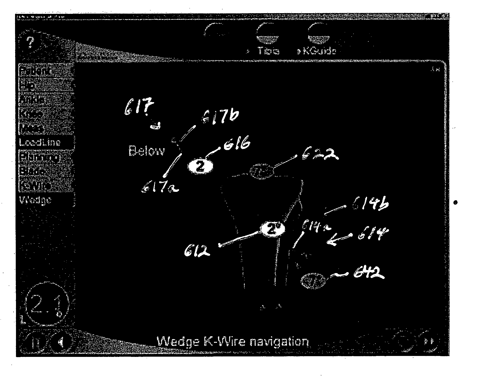
[0037] Prior to the surgery, the surgeon has determined both the desired correction angle and, if different, the desired angle of the wedge to be removed and this information is input into the memory of the surgical navigation system for use during the surgery, as will be described below.

[0038] The surgeon surgically opens the knee with standard incisions f...


PUM


Abstract

The invention provides methods and apparatus for accurately cutting bones with a surgical cutting device, such as a sagittal saw, using a surgical navigation system without use of a complex cutting jig. A surgical navigation system is used to navigate a guide tube to be used to drill a k-wire into the bone. The k-wire will act as a guide to control at least one degree of freedom of a saw blade for making a cut in the bone. In an exemplary high tibial osteotomy procedure, in which two intersecting planar cuts must be made in the tibia in order to remove a wedge of bone, a surgical navigation marker is mounted on the guide tube. The surgeon uses the surgical navigation system to navigate the guide tube to the desired varus-valgus angle and height of the first cut and then drills a k-wire into the tibia at that varus-valgus angle using the guide tube. The process is repeated for the second cut. The surgeon then uses the two k-wires as guides for controlling the varus-valgus angle of a sagittal saw for the two planar cuts. The surgeon rests the saw blade flat on the respective k-wire to define the varus-valgus angle of the cut. The saw itself also is navigated, with the surgical navigation system providing a display showing the surgeon at least (1) the varus-valgus angle, (2) the cut depth, and (3) the anterior-posterior slope. The anterior-posterior slope and the depth of the cut is controlled freehand by the surgeon.

Description

FIELD OF THE INVENTION [0001] The present invention relates to surgical navigation systems, often called localization devices. More particularly, the present invention relates to methods and apparatus for navigating a cutting tool during orthopedic surgery using a surgical navigation system. BACKGROUND OF THE INVENTION [0002] In an exemplary surgical navigation system 100 such as illustrated in FIG. 1, at least two sensors 114a, 114b (e.g., infrared cameras) mounted in a housing 128 are used to detect a plurality of markers 116a, 116b, 116c, 116d, 116e that can be mounted on the patient's bones 105a, 105b and / or on surgical tools 124. More particularly, the cameras 114a, 114b are coupled to a computer 112 that analyzes the images obtained by the cameras and detects the positions and orientations of the various bones and / or tools bearing the markers during the surgery and calculates and displays useful information for performing the surgery to the surgeon on a monitor 122. The comput...

Claims


Application Information

Patent Timeline
IPC IPC(8): A61F5/00
CPCA61B17/152A61B17/157A61B17/1764A61B19/52A61B19/5244A61B19/56A61B2019/5255A61B2019/5483A61B34/20A61B34/25A61B90/36A61B2034/2055A61B2090/3983
Inventor BAUR, WILHELMGRAF, SABINE CONSTANZEPINZUTI, JEAN-BAPTISTE
Owner AESCULAP AG
Why Eureka
Try Eureka