Decoupling storage controller cache read replacement from write retirement

a storage controller and read replacement technology, applied in the field of data storage controllers, can solve the problems of reducing the size of the secondary cache, unable to free up space quickly, and unable to modify the modified track,

Inactive Publication Date: 2007-05-24
IBM CORP
View PDF16 Cites 58 Cited by
  • Summary
  • Abstract
  • Description
  • Claims
  • Application Information

AI Technical Summary

Benefits of technology

[0009] The present invention provides system, method and program product for more efficient cache management discard / destage policies. Prior to or during the scan, modified (write) data entries are moved to the most recently used (MRU) end of the list, allowing the scan to proceed in an efficient manner and not have to skip over modified data entries. Optionally, a status bit may be associated with each modified data entry. When the entry is moved to the MRU end of the A list, its status bit is changed from an initial state (such as 0) to a second state (such as 1), indicating that it is a candidate to be discarded. If a write track requested to be accessed is found in the primary cache (a “hit”), the status bit of the corresponding A list entry is changed back to the first state, preventing the track from being discarded. Thus, write tracks are allowed to remain in the primary cache only as long as necessary.

Problems solved by technology

Typically, the secondary cache is smaller than the primary cache due to the cost of NVS memory.
Even if the modified data entries are not skipped over but are destaged, they may not be able to free up space quickly enough for the new entries; and as long as the destage is in progress, these modified entries will have to be skipped over.
As a result, during heavy write loads, some modified tracks may be modified several times and remain in the secondary cache for a relatively long time.
When there are many modified tracks in the primary cache, list scans have to skip over many entries and may not be able to identify enough unmodified tracks to discard to make room for new tracks.
As will be appreciated, skipping over so many cached tracks takes a significant amount of time and wastes processor cycles.

Method used


Image

  • Decoupling storage controller cache read replacement from write retirement
  • Decoupling storage controller cache read replacement from write retirement
  • Decoupling storage controller cache read replacement from write retirement

Examples


Embodiment Construction

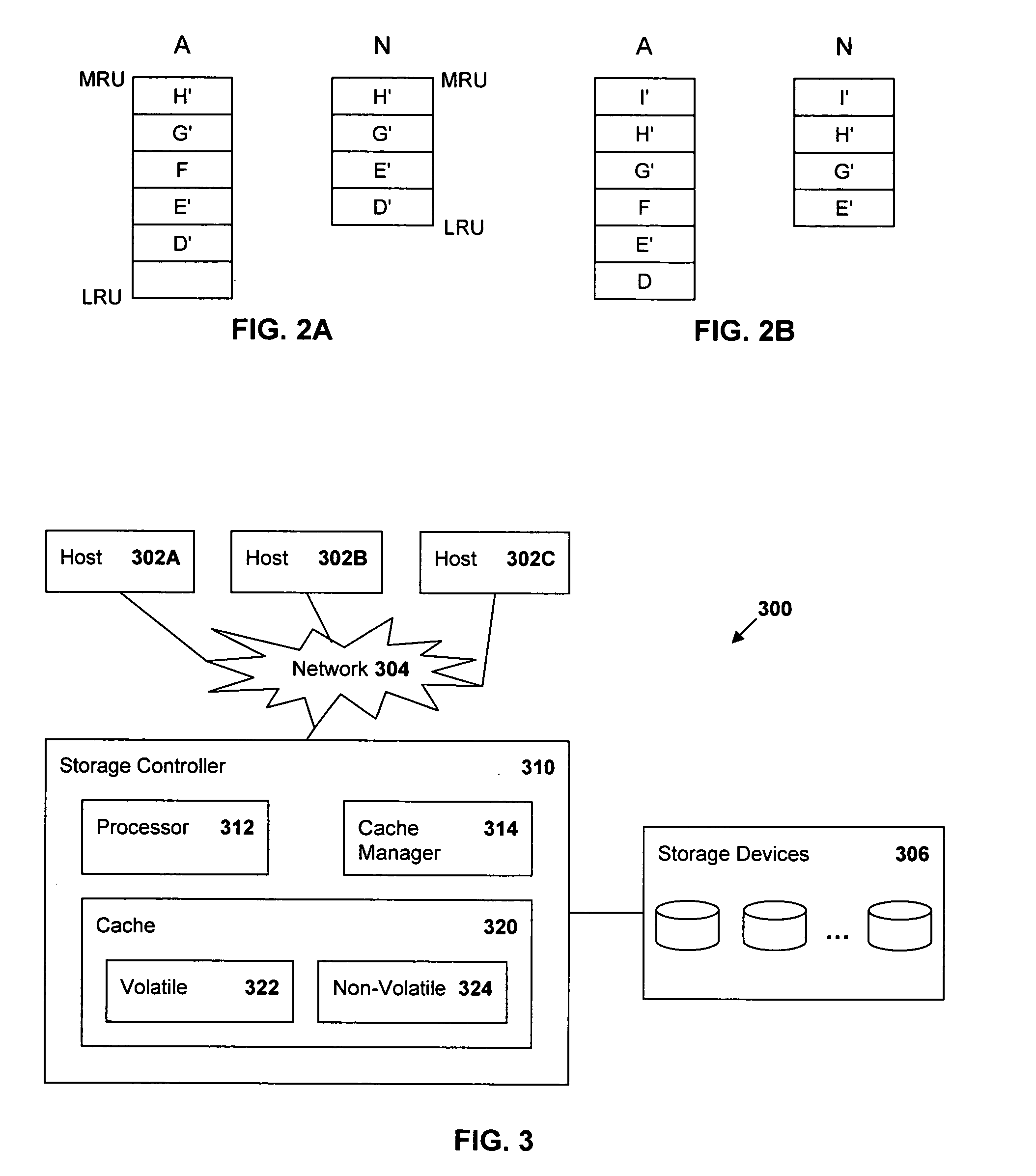
[0017]FIG. 3 is a block diagram of a data processing environment 300 in which the present invention may be implemented. A storage controller 310 receives input / output (I / O) requests from one or more hosts 302A, 302B, 302C to which the storage controller 310 is attached through a network 304. The I / O requests are directed to tracks in a storage system 306 having disk drives in any of several configurations, such as a Direct Access Storage Device (DASD), a Redundant Array of Independent Disks (RAID Array), Just A Bunch of Disks (JBOD), etc. The storage controller 310 includes a processor 312, a cache manager 314 and a cache 320. The cache manager 314 may comprise either a hardware component or a software / firmware component executed by the processor 312 to manage the cache 320. The cache 320 comprises a first portion and a second portion. In one embodiment, the first cache portion is a volatile storage 322 and the second cache portion is non-volatile storage (NVS) 324. The cache manage...


PUM


Abstract

In a data storage controller, accessed tracks are temporarily stored in a cache, with write data being stored in a first cache (such as a volatile cache) and a second cache and read data being stored in a second cache (such as a non-volatile cache). Corresponding least recently used (LRU) lists are maintained to hold entries identifying the tracks stored in the caches. When the list holding entries for the first cache (the A list) is full, the list is scanned to identify unmodified (read) data which can be discarded from the cache to make room for new data. Prior to or during the scan, modified (write) data entries are moved to the most recently used (MRU) end of the list, allowing the scans to proceed in an efficient manner and reducing the number of times the scan has to skip over modified entries Optionally, a status bit may be associated with each modified data entry. When the modified entry is moved to the MRU end of the A list without being requested to be read, its status bit is changed from an initial state (such as 0) to a second state (such as 1), indicating that it is a candidate to be discarded. If the status bit is already set to the second state (such as 1), then it is left unchanged. If a modified track is moved to the MRU end of the A list as a result of being requested to be read, the status bit of the corresponding A list entry is changed back to the first state, preventing the track from being discarded. Thus, write tracks are allowed to remain in the first cache only as long as necessary.

Description

TECHNICAL FIELD [0001] The present invention relates generally to data storage controllers and, in particular, to establishing cache discard and destage policies. BACKGROUND ART [0002] A data storage controller, such as an International Business Machines Enterprise Storage Server®, receives input / output (I / O) requests directed toward an attached storage system. The attached storage system may comprise one or more enclosures including numerous interconnected disk drives, such as a Direct Access Storage Device (DASD), Redundant Array of Independent Disks (RAID Array), Just A Bunch of Disks (JBOD), etc. If I / O read and write requests are received at a faster rate then they can be processed, then the storage controller will queue the I / O requests in a primary cache, which may comprise one or more gigabytes of volatile storage, such as random access memory (RAM), dynamic random access memory (DRAM), etc. A copy of certain modified (write) data may also by placed in a secondary, non-volat...

Claims


Application Information

Patent Timeline
Patent Type & Authority Applications(United States)
IPC IPC(8): G06F12/00G06F13/00
CPCG06F12/0866G06F12/123G06F12/127
Inventor LOWE, STEVEN R.MODHA, DHARMENDRA S.GILL, BINNY S.HYDE, JOSEPH S.
Owner IBM CORP
Why Eureka
Try Eureka