Hydrostatic drive system

Inactive Publication Date: 2007-05-31
LINDE HYDRAULICS
View PDF7 Cites 3 Cited by
  • Summary
  • Abstract
  • Description
  • Claims
  • Application Information

AI Technical Summary

Benefits of technology

[0010] The invention teaches that this object can be accomplished by integrating the pressure limiting device and the feeder device into one valve unit. The invention therefore teaches that the pressure limiting device in which the pressure can be increased and the feeder device are combined in a single valve unit. As a result, only one installation space is necessary for the pressure limiting device and the feeder device. A simple routing of the hydraulic lines and conduits is also achieved. Overall, therefore, a drive system of the invention can be realized with less construction effort and expense and requires less installation space.
[0011] In one advantageous embodiment of the invention, the valve unit is a combined pressure control and feeder valve. The function of the pressure limiting device in which the pressure can be increased and the function of the feeder device can, therefore, be achieved in a single valve unit, with little construction effort and expense.
[0012] In one development of the invention, to increase the response pressure, the valve unit is functionally connected with a piston device that acts to increase the response pressure of the pressure control unit. With a piston device of this type, which is in functional communication with a control surface of the pressure control valve of the valve unit that acts toward the closed position and, thus, toward an increase of the response pressure, it becomes possible to realize in a simple manner a pressure limiting device in which the pressure can be increased.

Problems solved by technology

As a result, only one installation space is necessary for the pressure limiting device and the feeder device.

Method used


Image

  • Hydrostatic drive system
  • Hydrostatic drive system

Examples


Embodiment Construction

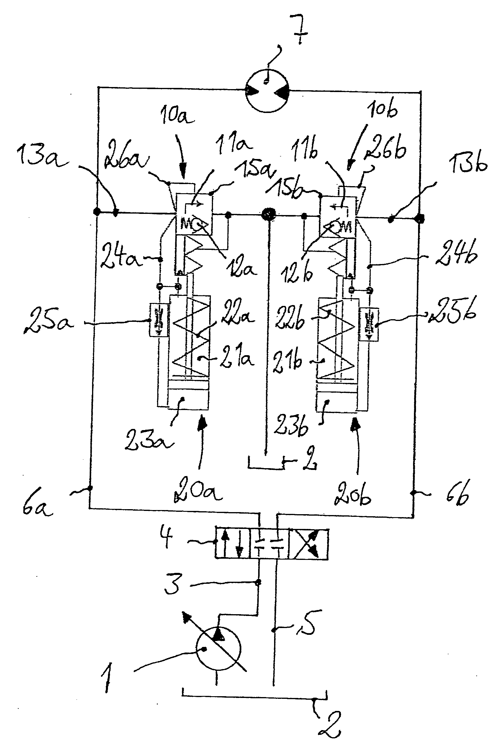
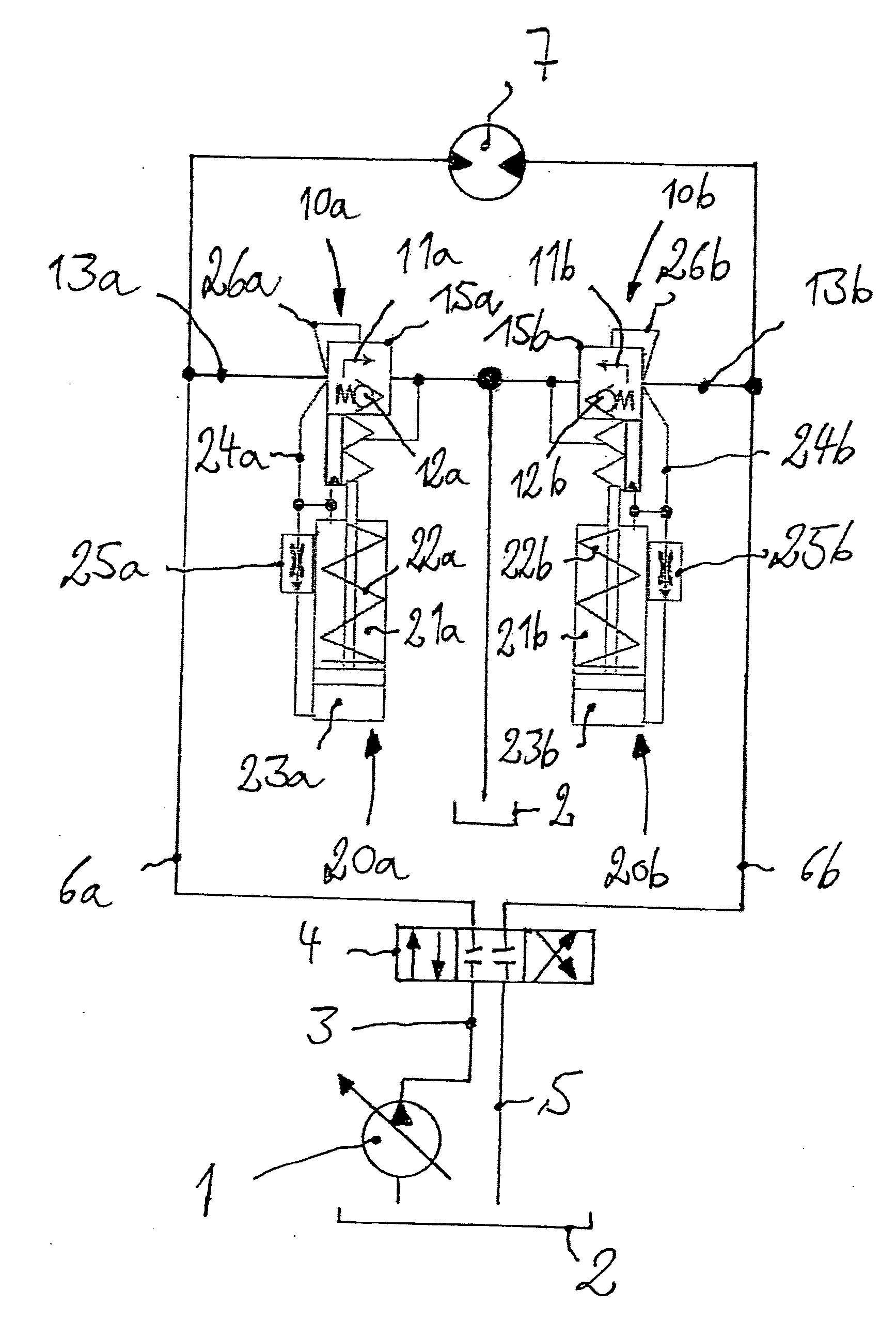
[0022] The drive system has a pump 1 that is realized in the form of a variable displacement pump, for example, a controlled, load-sensing pump, which sucks pressure fluid out of a reservoir 2 and delivers it into a delivery line 3. The delivery line 3 is connected to a control valve 4, which is also connected to a reservoir line 5 that leads to the reservoir 2, and is also connected to pressure fluid lines 6a, 6b that lead to the consumer 7, such as a hydraulic motor.

[0023] Associated with each pressure fluid line 6a, 6b is a valve unit 10a, 10b of the invention. Each valve unit 10a, 10b has a pressure limiting device 11a, 11b, in which the pressure can be increased, and a feeder device 12a, 12b. The pressure limiting device 11a, 11b in this case is located in a first control pressure line 13a, 13b, which is connected to the pressure fluid line 6a, 6b and leads to the reservoir 2.

[0024] The valve unit 10a, 10b of the invention is, in this case, realized in the form of a combined ...


PUM


Abstract

A hydrostatic drive system has a consumer (7), in particular a hydraulic motor, located in the open circuit. Associated with the consumer (7) is at least one pressure limiting device (11a; 11b) that can be actuated in the braking phase for the generation of a braking pressure that is present on the discharge side of the consumer (7) from a minimum response pressure in the direction of an increase of the response pressure. A feeder device (12a; 12b) provides a feed of pressure fluid into the admission side of the consumer (7). The pressure limiting device (11a; 11b) and the feeder device (12a; 12b) are integrated into a valve unit (10a; 10b).

Description

CROSS REFERENCE TO RELATED APPLICATION [0001] This application claims priority to German Application No. 10 2005 053 265.9, filed Nov. 8, 2005, which application is herein incorporated by reference in its entirety. BACKGROUND OF THE INVENTION [0002] 1. Field of the Invention [0003] This invention relates to a hydrostatic drive system with a consumer, such as a hydraulic motor, located in an open circuit. Associated with the consumer is at least one pressure limiting device that can be actuated in the braking phase for generation of a braking pressure on the discharge side of the consumer. The braking pressure can change from a minimum response pressure to an increase in the response pressure. A feeder device provides a feed of pressure fluid into the admission side of the consumer. [0004] 2. Technical Considerations [0005] Drive systems of this type are used, for example, as slewing gear drives for mobile machines, such as excavators. To decelerate the consumer, a control valve that...

Claims


Application Information

Patent Timeline
IPC IPC(8): F16D31/02F16H61/40F16H61/4017F16H61/4131
CPCE02F9/128E02F9/2207E02F9/226F15B7/006F15B7/008F15B2211/20546F15B2211/30525F15B2211/50527F15B2211/613F15B2211/7058F16H61/4017F16H61/4131F16H61/4148F16H61/4157
Inventor DOLGER, MARCUSLOBB-RABE, HENNING
Owner LINDE HYDRAULICS
Why Eureka
Try Eureka