Method and apparatus for drilling curved boreholes

Inactive Publication Date: 2007-05-31
SUNSTONE TECH
View PDF3 Cites 8 Cited by
  • Summary
  • Abstract
  • Description
  • Claims
  • Application Information

AI Technical Summary

Benefits of technology

[0009] It is an object of the present invention to provide a rotary steerable tool that improves the flow characteristics

Problems solved by technology

In practice, though, steering a drill bit with sufficient precision to create the desired curvature has proven difficult.
But because the bent housing is a fixed part of the drill string, a curved hole can be drilled with these conventional devices only when the drill string is not rotating.
Such a fluid restriction can increase the pressure above the too

Method used


Image

  • Method and apparatus for drilling curved boreholes
  • Method and apparatus for drilling curved boreholes
  • Method and apparatus for drilling curved boreholes

Examples


Example

[0028] As used herein, “fluid” means a source or means of supplying pressure and shall include without limitation hydraulic fluid, water, high-pressure compressed air, and similar sources of pressure.

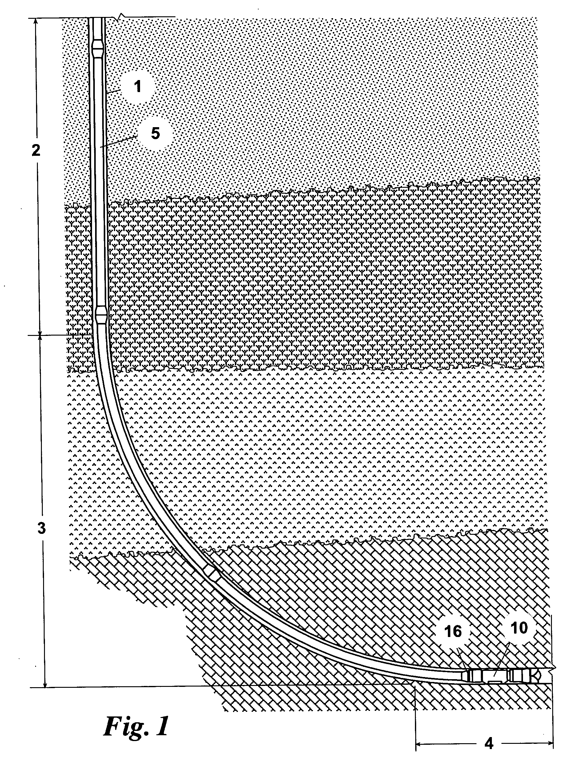
[0029] Referring now to FIG. 1, there is shown well bore 1 comprising the vertical borehole 2, non-linear borehole 3, and horizontal borehole 4, described above. Well bore 1 extends downwardly beneath the surface of the ground through numerous and varied subterranean strata, some of which may be oil-bearing. Drill string 5 extends vertically downward in well bore 1 and connects with drill pipe 16. Drill pipe 16, in turn, connects to the improved rotary steerable tool 10 of the present invention.

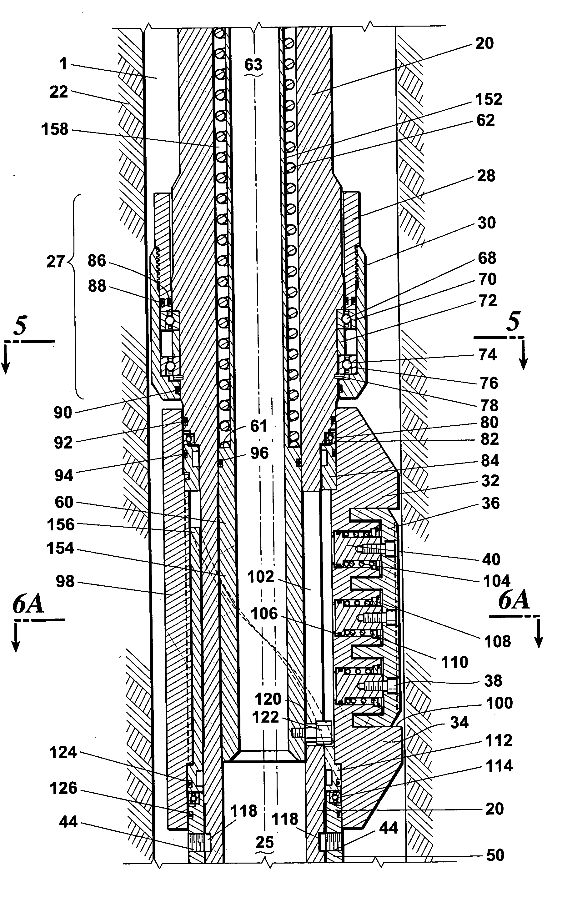
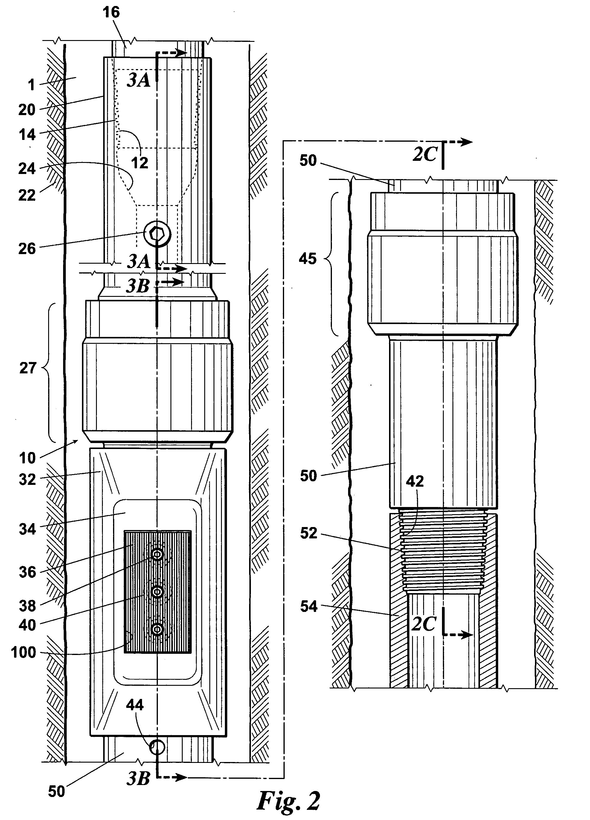
[0030]FIG. 2 depicts the improved rotary steerable tool 10 of the present invention, which has been modified and ported in a manner later to be described. Rotary steerable tool 10 has upper mandrel 20 with female threads 12 on one end that mate with male threads 14 on the end of a drill pipe, s...


PUM


Abstract

The invention is an rotary steerable tool. The improved rotary steerable tool comprises a control tube that slides vertical within a mandrel in response to changes in drilling fluid pressure, thereby opening and closing a channel between the mandrel and a piston chamber in a rotationally isolated sleeve. With the channel open, a piston in the piston chamber is exposed to the drilling fluid. When the drilling pressure is sufficient to cause the piston to move, the piston forces a deflection pad outward. After the deflection pad engages a borehole wall, any additional increases in pressure force the opposing side of sleeve toward the opposite wall, thereby tilting the direction of any attached drill bit. An optional guide lug and alignment sleeve orient the deflection pad with respect to other components.

Description

CROSS-REFERENCE TO RELATED APPLICATION [0001] The present invention is an improvement over the invention disclosed and claimed in my prior U.S. Pat. No. 5,941,321, issued Aug. 24, 1999 on a “METHOD AND APPARATUS FOR SHORT RADIUS DRILLING OF CURVED BOREHOLES.”FIELD OF THE INVENTION [0002] This invention is related to a method and apparatus for boring a hole in the earth, or in material having similar characteristics. More particularly, this invention relates to an apparatus for boring a hole having at least one non-linear segment. BACKGROUND OF THE INVENTION [0003] Horizontal drilling technology has come a long way in the past 20 years, and is now an accepted drilling method that has numerous benefits for the recovery of hydrocarbons. Horizontal drilling can be used as both an exploration tool and as a completion technique. The benefits of horizontal drilling when used as part of a completion method include increased drainage area, connecting fracture permeability to the well bore, a...

Claims


Application Information

Patent Timeline
IPC IPC(8): E21B7/04
CPCE21B7/062
Inventor HUGHES, WILLIAM JAMESBRIGGS, GARY MARSHALL
Owner SUNSTONE TECH
Why Eureka
Try Eureka