Quick coupling device

a coupling device and quick technology, applied in the field of quick coupling devices, can solve the problems of affecting the quality of the coupling, and affecting the performance of the coupling, and achieve the effect of quick coupling devi

Inactive Publication Date: 2007-05-31
LEGRIS
View PDF9 Cites 43 Cited by
  • Summary
  • Abstract
  • Description
  • Claims
  • Application Information

AI Technical Summary

Benefits of technology

[0004] It would thus be advantageous to have a quick coupling device presen

Problems solved by technology

The body, which is the main part of the coupling device, is then liable to suffer deformations that can spoil the quality of the coupling, in particular concerning the firmness with which the second duct is retained and the leaktightness of the

Method used


Image

  • Quick coupling device
  • Quick coupling device
  • Quick coupling device

Examples


first embodiment

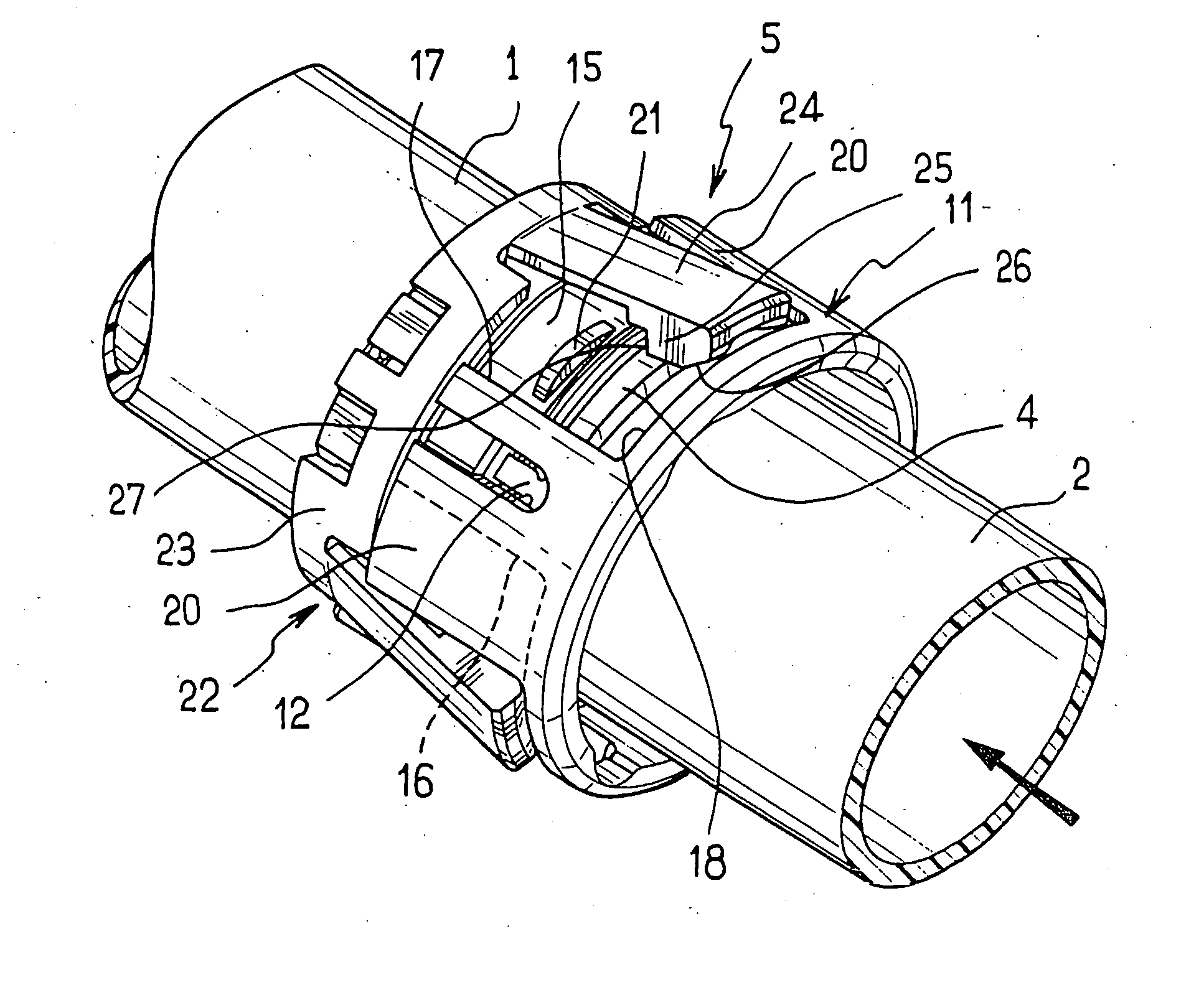
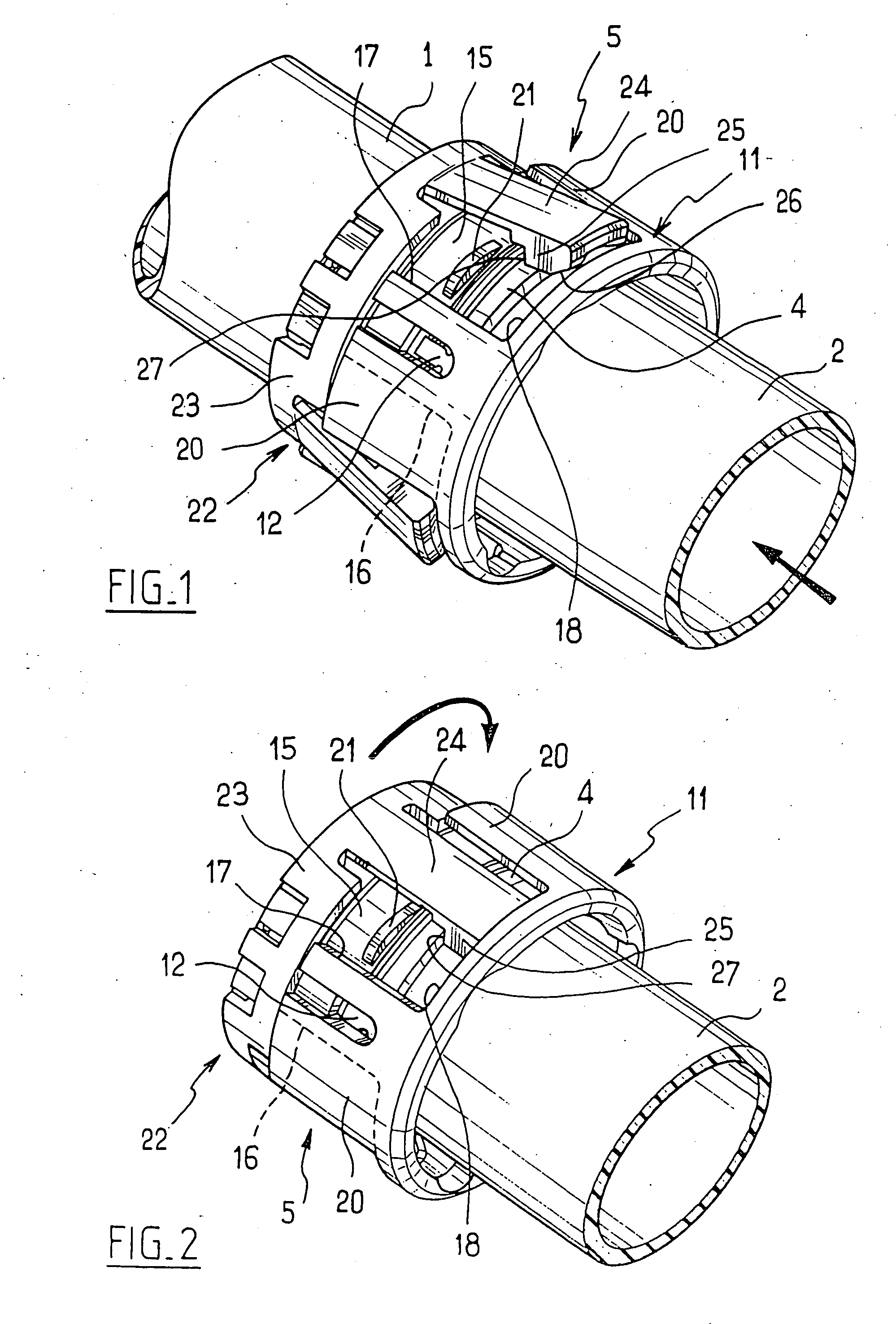
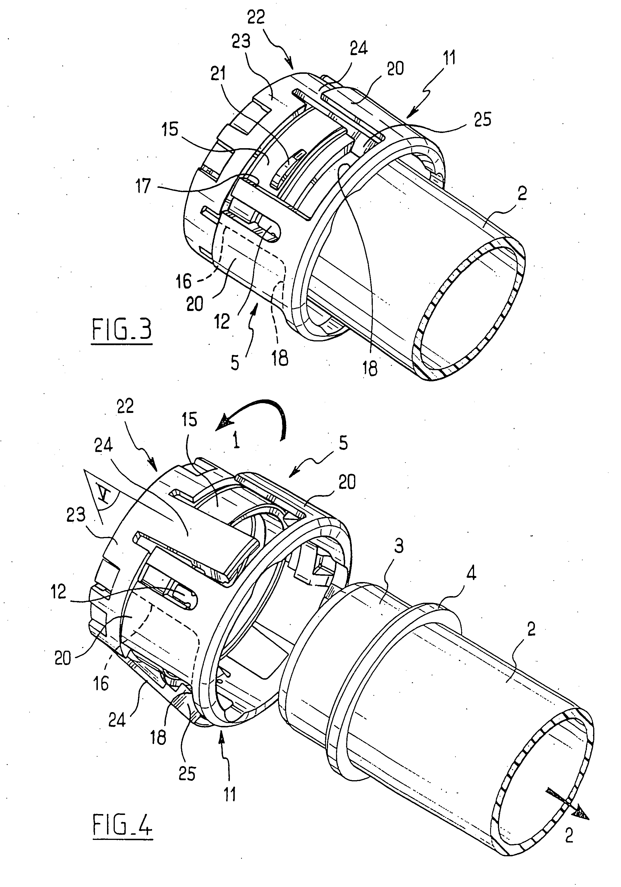
[0027] With reference to FIGS. 1 to 6, the quick coupling device constituting the invention is for enabling a first duct 1 (visible only in FIG. 1) to be connected to a second duct 2. The duct 2 has an end 3 provided on the outside with an annular bead 4. By way of example, the ducts 1 and 2 are pipes in a circuit for transporting a fluid, such as air, or they are secured one to a member for issuing fluid, such as a pump, and the other to a member for receiving fluid, such as a tank or a turbine. In this case, the ducts 1 and 2 are ducts of thermoplastic material.

[0028] The quick coupling device comprises a body given overall reference 5 which is subdivided into a link section 6 for linking to the duct 1, and into a connection section 7 arranged to receive the end 3 of the duct 2.

[0029] In this example, the link section 6 comprises a ring 8 that presents, remote from the connection section 7, an end face 9 having a collar 10 extending in axial projection therefrom (visible in parti...

second embodiment

[0046] Elements that are identical or analogous to those described above are given identical numerical references in the following description of the second embodiment, which is described with reference to FIGS. 7 to 9.

[0047] The coupling device in accordance with the second embodiment comprises a body 5 and a retaining member 22.

[0048] The body 5, as in the first embodiment, comprises a link section 6 and a connection section 7.

[0049] The connection section 7 is surmounted by a rim 11 having setbacks 15 formed therein, each defined by two lateral edges 16, 17 extending parallel to the axis of the coupling device, and by a transverse edge 18 extending perpendicularly to the axis of the coupling device towards the free end of the rim 11. Each setback opens out away from the transverse edge 18 to a cylindrical bearing surface 19.

[0050] A flap 120 extends over the setback 15 from the lateral edge 16 and the transverse edge 18.

[0051] In the vicinity of the lateral edge 16 of each se...


PUM


Abstract

A quick coupling device comprising a body (5) axially subdivided into a link section (6) for linking to a first duct (1), and a connection section (7) arranged to receive in leaktight manner one end of a second duct (2), the body being associated with a retaining member (22) possessing tabs (24) that are elastically deformable between a state of gripping an outer bead (4) on the end of the second duct, and a state of releasing the bead, the retaining member being mounted on the body to turn between a free deformation position in which the tabs can deform between their two states, and at least one holding position in which the tabs cooperate with a surface (20, 21) that is secured to the body and that holds the tabs in one of their two states.

Description

[0001] The present invention relates to a quick coupling device suitable for use, for example, in a circuit for transporting a fluid, such as air. BACKGROUND OF THE INVENTION [0002] There exist quick coupling devices comprising a body that is axially subdivided into a link section for linking to a first duct and a connection section arranged to receive in leaktight manner one end of a second duct. The body is associated with a retaining member possessing tabs that are elastically deformable between a state for gripping an outer bead on the end of the second duct, and a state for releasing the bead. The tabs are made integrally with the body. It is known to mount a locking ring on the body, which ring can pivot or slide between a position in which the ring leaves the tabs free to deform between their two states, and a position in which the ring holds the tabs in their gripping state. [0003] In order to enable the tabs to deform, it is necessary for the body to be made of a material t...

Claims


Application Information

Patent Timeline
IPC IPC(8): F16L37/18F16L37/098F16L37/12F16L37/133
CPCF16L37/0985F16L37/133F24F13/0209Y10S285/921
Inventor PODER, PHILIPPE
Owner LEGRIS
Why Eureka
Try Eureka