Phosphor plate and light emitting device having same

a technology of light emitting device and phosphor plate, which is applied in the direction of discharge tube luminescnet screen, discharge tube/lamp details, electric discharge lamps, etc., can solve the problems of light absorption loss, light extraction efficiency reduction, wavelength conversion efficiency of phosphor, etc., and achieve the effect of improving light extraction efficiency and improving uneven emission color

Inactive Publication Date: 2007-05-31
TOYODA GOSEI CO LTD
View PDF4 Cites 98 Cited by
  • Summary
  • Abstract
  • Description
  • Claims
  • Application Information

AI Technical Summary

Benefits of technology

[0028] In the invention, the light extraction efficiency can be enhanced, the high-brightness emission can be obtained over a long time, and the unevenness in emission color can be improved.

Problems solved by technology

(1) A part of light emitted from the LED element is absorbed in the sealing material to cause light absorption loss.
Therefore, the light extraction efficiency lowers.
Therefore, the wavelength conversion efficiency of the phosphor lowers so that the light emitting device cannot have high-brightness emission over a long time.
As a result, the wavelength conversion in the sealing material cannot be uniformly conducted to cause unevenness in emission color.

Method used


Image

  • Phosphor plate and light emitting device having same
  • Phosphor plate and light emitting device having same
  • Phosphor plate and light emitting device having same

Examples


first embodiment

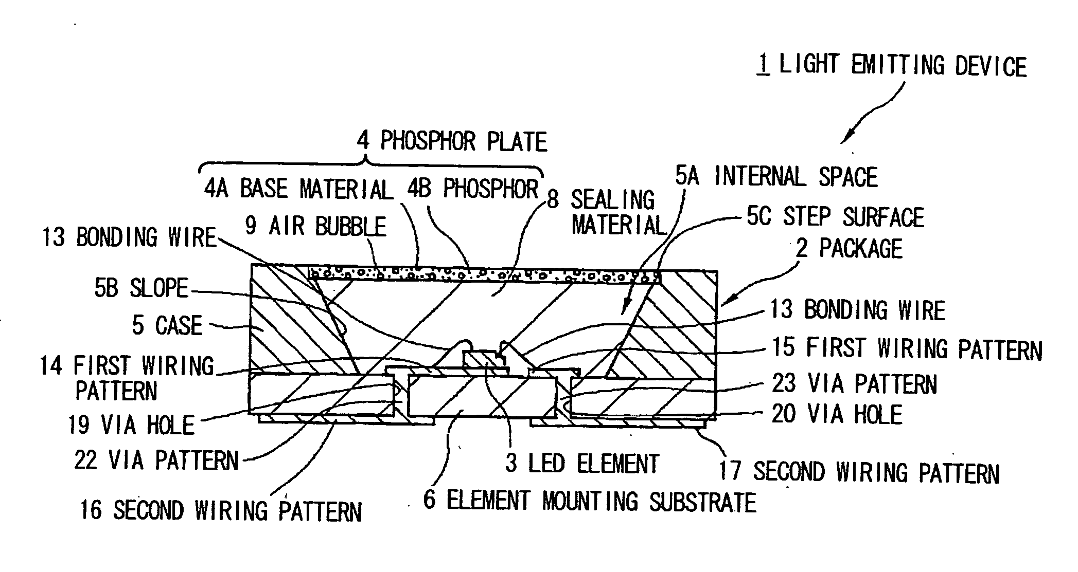
[0035]FIG. 1A is a cross sectional view showing a light emitting device in the first preferred embodiment according to the invention. FIG. 1B is a cross sectional view showing an LED element in FIG. 1A.

[0036] Light Emitting Device

[0037] As shown in FIG. 1A, the light emitting device 1 comprises: a package 2 for housing an LED element 3; the LED element 3 housed in the package 2; a sealing material 8 which is filled in the package 2 and seals the LED element 3; a phosphor plate 4 which is disposed on the light extraction side of the LED element 3 while covering the sealing material 8.

[0038] Package

[0039] As shown in FIG. 1A, the package 2 comprises a case 5 which houses the LED element 3, and an element mounting substrate 6 which covers an opening on one side (i.e., downside in FIG. 1A) of the case 5.

[0040] Case

[0041] As shown in FIG. 1A, the case 5 comprises an internal space 5A which is formed circular in plain view and opened in the direction from the substrate side to the l...

second embodiment

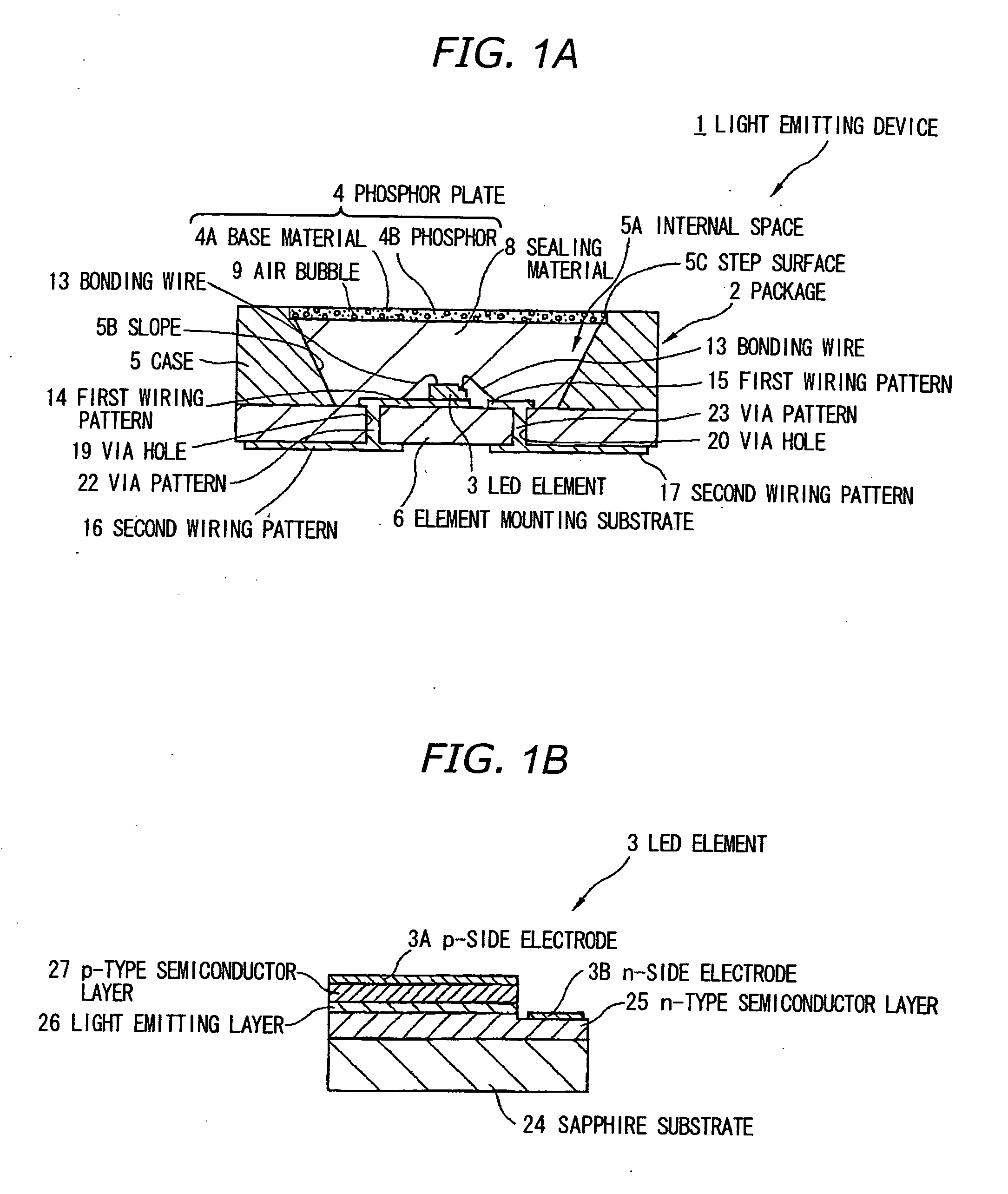
[0062]FIG. 2 is a cross sectional view showing a light emitting device in the second preferred embodiment according to the invention. In FIG. 2, like components are indicated by using the same numerals as in FIGS. 1A and 1B and the detailed explanations are omitted below.

[0063] As shown in FIG. 2, the light emitting device 31 has the feature that a bead 32 is used as the converter of light traveling direction.

[0064] The base material 4A includes the beads 32 (with a refractive index of n3=1.4), which is formed of silica (SiO2) etc., to covert the traveling direction of blue light emitted from the LED element 3. The bead 32 is, e.g., about 20 to 100 μm in diameter and accounts for 2 to 3% to the total volume of the phosphor plate 4.

[0065] Effects of the Second Embodiment

[0066] The same effects (1) to (3) as the first embodiment can be obtained by the above second embodiment.

third embodiment

[0067]FIG. 3A is a cross sectional view showing a light emitting device in the third preferred embodiment according to the invention. FIG. 3B is a perspective view showing a phosphor plate in FIG. 3A. In FIGS. 3A and 3B, like components are indicated by using the same numerals as in FIGS. 1A and 1B and the detailed explanations are omitted below.

[0068] As shown in FIG. 3A, the light emitting device 41 has the feature that it comprises a phosphor plate 42 with a through hole 42 formed therein.

[0069] The through hole 42A of the phosphor plate 42 can be a circular hole opened on the light input surface and the light output surface of the phosphor plate 42. An air layer inside of the through hole 42A serves as a converter of light traveling direction.

[0070] In operation, a part of the blue light inputted in the phosphor plate 42 from the LED element 3 is reflected on the interface of the air layer inside of the through hole 42A and the base material 4A to change the traveling directi...


PUM


Abstract

A phosphor plate has a wavelength conversion plate member formed of a base material with a phosphor included therein. The phosphor is operable to radiate a wavelength-converted light by being excited by a light emitted from a light emitting element. The base material further has a converter of light travel direction.

Description

[0001] The present application is based on Japanese patent application No. 2005-311624, the entire contents of which are incorporated herein by reference. BACKGROUND OF THE INVENTION [0002] 1. Field of the Invention [0003] This invention relates to a phosphor plate to radiate a wavelength-converted light by being excited by light emitted from a light emitting element and to a light emitting device having the same. [0004] 2. Description of the Related Art [0005] A light emitting device is practically used which is operable to generate white light by the mixture of light emitted from an LED (=light emitting diode) element and a wavelength-converted light radiated from a phosphor being excited by the emitted light. [0006] JP-A-2005-93712 discloses a light emitting device that comprises: a package having a case opened on the light extraction side; an LED element housed in the case; and a sealing material which seals the LED element and contains a phosphor. [0007] In the light emitting d...

Claims


Application Information

Patent Timeline
Patent Type & Authority Applications(United States)
IPC IPC(8): H01J1/62H01L33/50H01L33/56H01L33/32H01L33/60H01L33/62
CPCH01L33/486H01L33/501H01L2933/0091H01L2224/48091H01L2924/00014H01L2224/49107
Inventor HAYASHI, TOSHIMASAKATO, HIDEAKIKAWAGUCHI, HIROAKINARITA, TAKUMI
Owner TOYODA GOSEI CO LTD
Why Eureka
Try Eureka