Plasma display panel

a technology of display panel and plasma, which is applied in the direction of gas discharge electrodes, gas discharge vessels/containers, gas-filled discharge tubes, etc., can solve the problems of low discharge efficiency, high energy consumption, and inability to increase the luminous efficiency of the beam

Inactive Publication Date: 2007-05-31
SAMSUNG SDI CO LTD
View PDF5 Cites 11 Cited by
  • Summary
  • Abstract
  • Description
  • Claims
  • Application Information

AI Technical Summary

Problems solved by technology

However, in this procedure, ions that do not increase luminous efficiency are generated, much energy is consumed in accelerating the ions such that discharge efficiency is very low due to an unnecessary energy loss.
In addition, due to a discharge characteristic, if discharge cells are made smaller, a problem with reliability occurs, in that discharge efficiency is further lowered and an unstable discharge occurs.

Method used


Image

  • Plasma display panel
  • Plasma display panel
  • Plasma display panel

Examples


Embodiment Construction

[0027] The present embodiments will now be described more fully with reference to the accompanying drawings, in which exemplary embodiments are shown.

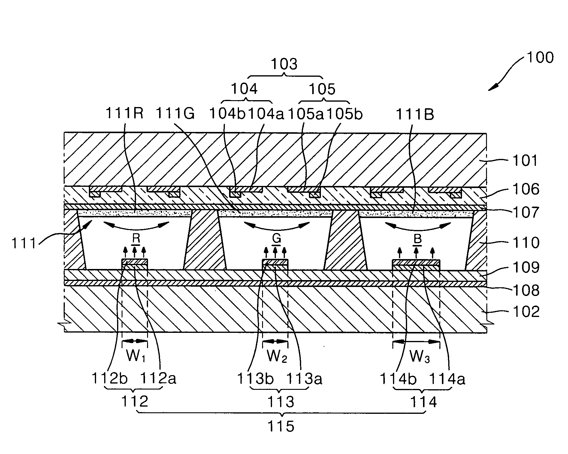
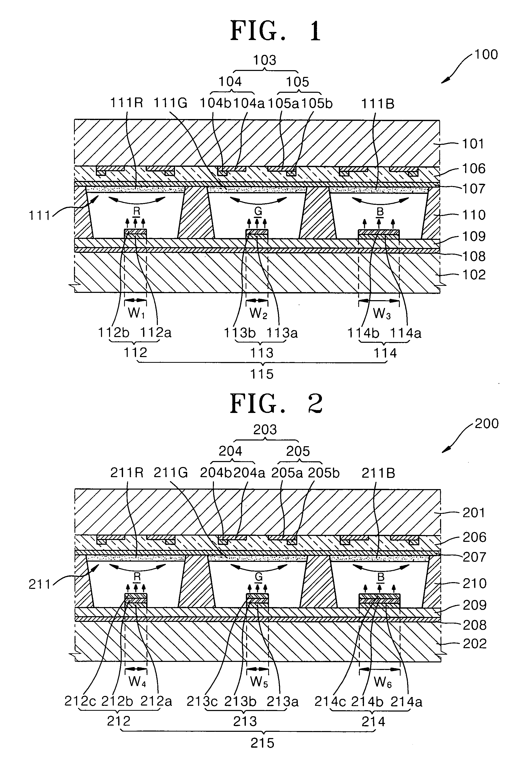
[0028]FIG. 1 illustrates a plasma display panel (PDP) 100 according to an embodiment. Referring to FIG. 1, the PDP 100 includes a front substrate 101 and a rear substrate 102 parallel to the front substrate 101. The front substrate 101 and the rear substrate 102 form a discharge space sealed by a frit glass coated along edges of opposed inner surfaces.

[0029] The front substrate 101 may be a transparent substrate such as, for example, a soda lime glass, a semi-transmitted type substrate, a reflective type substrate or a colored substrate. A sustain discharge electrode pair 103 is formed on an inner surface of the front substrate 101. The sustain discharge electrode pair 103 includes an X electrode 104 and a Y electrode 105. A pair of the X electrode 104 and the Y electrode 105 is disposed by discharge cells.

[0030] The X electrode 104...


PUM


Abstract

Provided is a plasma display panel. The plasma display panel comprises: a front substrate; a rear substrate opposing the front substrate; a plurality of discharge electrodes disposed inside the substrates; a plurality of light emitting layers formed inside discharge cells; and an electron emitting source disposed inside the discharge cells so as to supply electrons, the area of electron emitting source differing in each of the discharge cells. The electron emitting source is installed in the discharge cells such that an electron emission characteristic is improved and brightness and luminous efficiency of the plasma display panel can be improved. The area of the electron emitting source or the number of electron emitting sources in each of the discharge cells differs such that a discharge characteristic in the discharge cells having lower brightness can be improved.

Description

CROSS-REFERENCE TO RELATED APPLICATION [0001] This application claims the priority of Korean Patent Application No. 10-2005-0115878, filed on Nov. 30, 2005, in the Korean Intellectual Property Office, the disclosure of which is incorporated herein in its entirety by reference. BACKGROUND OF THE INVENTION [0002] 1. Field of the Invention [0003] The present embodiments relate to a plasma display panel (PDP), and more particularly, to a PDP in which sizes of electron emitting sources differ in each of discharge cells such that a discharge characteristic is improved. [0004] 2. Description of the Related Art [0005] Generally, plasma display panels (PDP) are flat display devices in which a discharge gas is injected into a plurality of substrates and sealed between the substrates and, if a gas discharge occurs due to a voltage applied to a plurality of discharge electrodes, a phosphor layer is excited by ultraviolet rays generated in a discharge process and visible rays are emitted such th...

Claims


Application Information

Patent Timeline
Patent Type & Authority Applications(United States)
IPC IPC(8): H01J17/49H01J11/14H01J11/22H01J11/24H01J11/34
CPCH01J11/12H01J11/28H01J11/40H01J11/20H01J11/42
Inventor JANG, SANG-HUNSON, SEUNG-HYUN
Owner SAMSUNG SDI CO LTD
Why Eureka
Try Eureka