Homeotropic alignment type semi-transmissive reflective liquid crystal display device

a liquid crystal display device and homeotropic alignment technology, applied in non-linear optics, instruments, optics, etc., can solve the problems of uneven display, inability to perform reflective display, and inability to align liquid crystal molecules in response to voltage applied

Active Publication Date: 2007-05-31
ORTUS TECH
View PDF8 Cites 51 Cited by
  • Summary
  • Abstract
  • Description
  • Claims
  • Application Information

AI Technical Summary

Benefits of technology

[0048] Since the liquid crystal display device according to the third aspect is of a homeotropic alignment type which has each of the plurality of pixel electrodes divided by the slit into a plurality of electrode portions such that the reflective layer is formed correspondingly to at least one of these electrode portions to form the reflective display region for reflecting light that enters from the observer side to the observer side and the other electrode portion(s) form(s) the transmissive display region for allowing light that enters ...

Problems solved by technology

In such a homeotropic alignment liquid crystal display device, the direction in which the liquid crystal molecules are aligned and lie down in response to the voltage applied, is not uniform throughout the pixels.
Therefore, the alignment state of the liquid crystal molecules varies from pixel to pixel, producing display unevenness.
However, ...

Method used


Image

  • Homeotropic alignment type semi-transmissive reflective liquid crystal display device
  • Homeotropic alignment type semi-transmissive reflective liquid crystal display device
  • Homeotropic alignment type semi-transmissive reflective liquid crystal display device

Examples


first embodiment

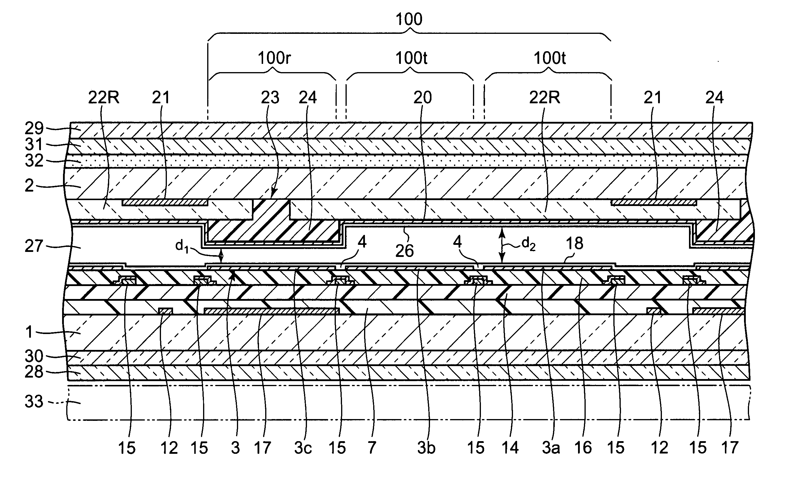
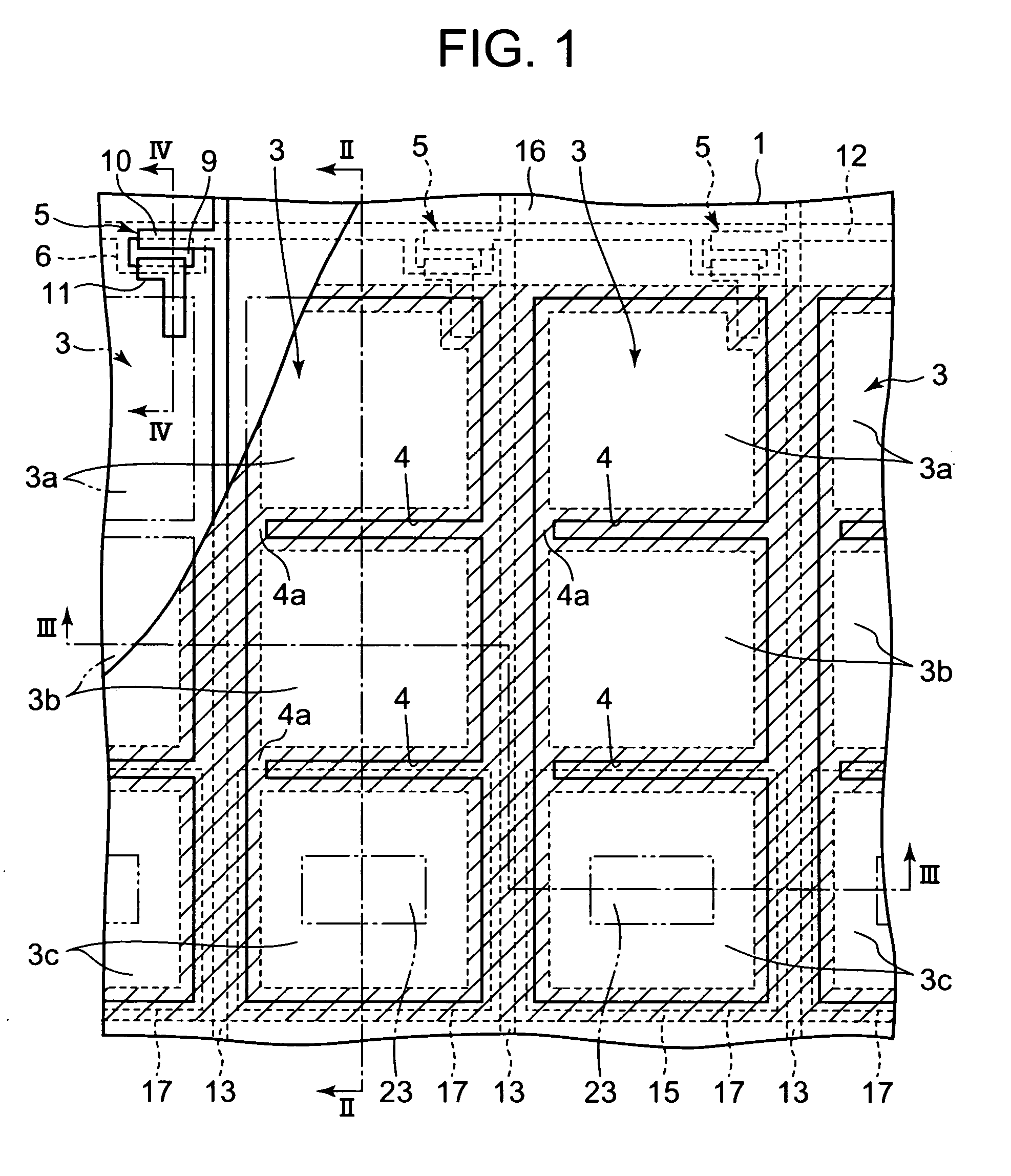
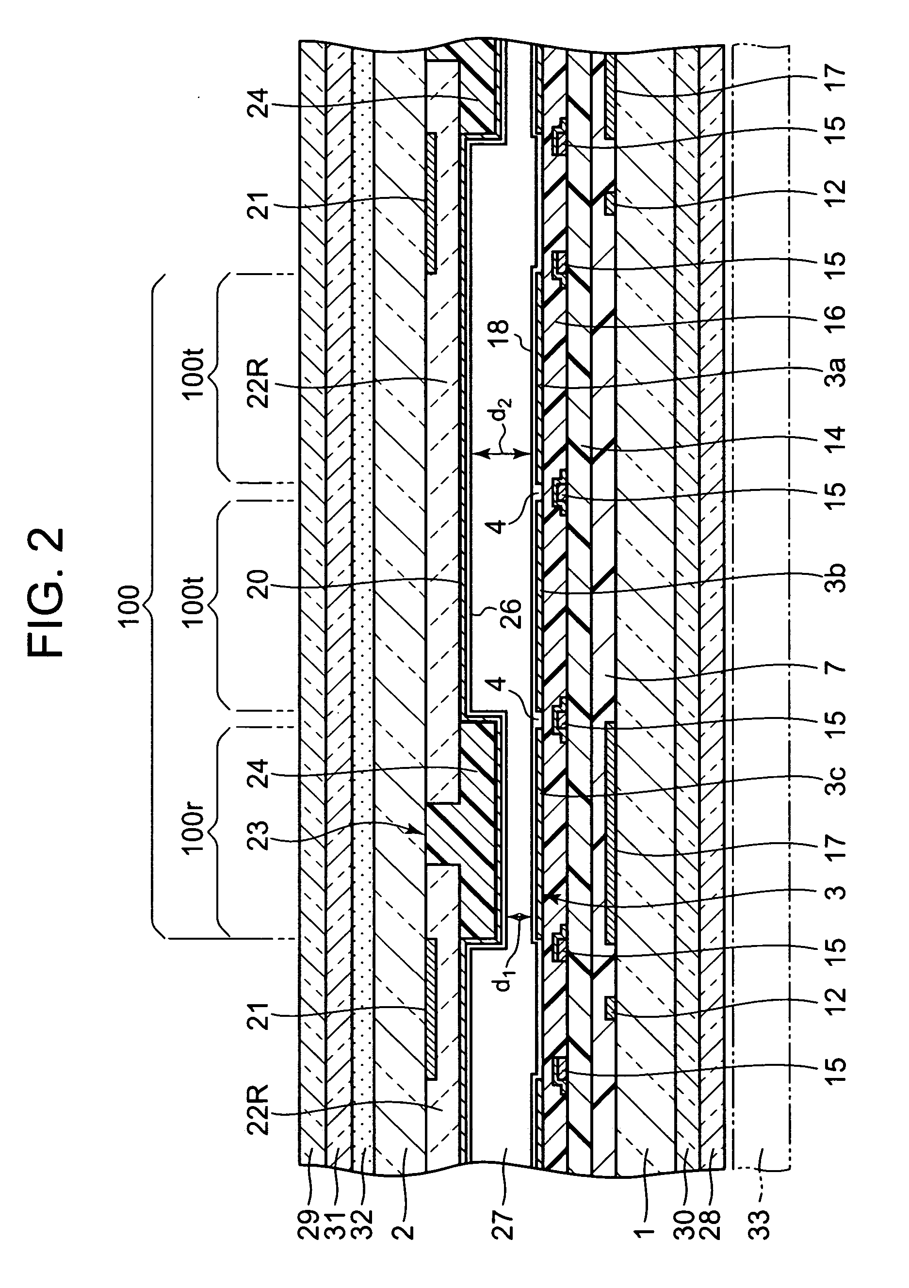
[0058] FIGS. 1 to 5 show the first embodiment of the resent invention, where FIG. 1 is a plan view of a part of a liquid crystal display device, FIGS. 2, 3, and 4 are cross sectional views as taken along a II-II line, a III-III line, and a IV-IV line of FIG. 1 respectively, and FIG. 5 is an expanded cross sectional view showing a part of FIG. 2 in expansion.

[0059] The present liquid crystal display device is a homeotropic alignment type active matrix liquid crystal display device, and comprises a pair of transparent substrates 1 and 2 arranged to face each other with a predetermined gap therebetween, and a liquid crystal layer 27 having negative dielectric anisotropy sealed in the gap between the pair of substrates 1 and 2, as show in FIGS. 1 to 5. Of the facing internal surfaces of the pair of substrates 1 and 2, the internal surface of one substrate, for example, the internal surface of the substrate (hereinafter referred to as rear substrate) 1 at the opposite side to the observ...

second embodiment

[0109] FIGS. 6 to 8 show the second embodiment of the present invention, where FIG. 6 is a plan view showing a part of a liquid crystal display device, FIG. 7 is a cross sectional view of the liquid crystal display device as taken along a VII-VII line of FIG. 6, and FIG. 8 is an expanded cross sectional view showing a part of FIG. 7 in expansion. In the present embodiment, the components corresponding to the above-described first embodiment will be denoted by the same reference numerals, and explanation for these components will be omitted.

[0110] The liquid crystal display device according to the present embodiment has a plurality of projections 25 provided on the internal surface of the front substrate 2 on which the opposing electrode 20 is formed, such that the projections 25 respectively correspond to the center of at least one electrode portion among the electrode portions 3a, 3b, and 3c separated by the slits 4 provided for each of the plurality of pixel electrodes 3 on the r...


PUM


Abstract

A liquid crystal display device has a pair of substrates disposed at an observer side and at the opposite side to the observer side, a plurality of pixel electrodes and an opposing electrode which are formed on the internal surfaces of the pair of substrates, a reflective layer, and liquid crystal sealed between these substrates. Each pixel electrode has a reflective display region corresponding to the reflective layer for reflecting light that enters from the observer side to the observer side, and a transmissive display region for allowing light that enters from the opposite side to pass therethrough to the observer side. A liquid crystal layer thickness adjusting layer is formed on the internal surface of the substrate at the observer side, for setting the liquid crystal layer thickness in the reflective display region to be smaller than the liquid crystal layer thickness in the transmissive display region.

Description

BACKGROUND OF THE INVENTION [0001] 1. Field of the Invention [0002] The present invention relates to a homeotropic alignment type liquid crystal display device which performs transmissive display and reflective display. [0003] 2. Description of the Related Art [0004] A homeotropic alignment type active matrix liquid crystal display device has been known. This liquid crystal display device comprises a pair of substrates facing each other with a predetermined gap therebetween, and a liquid crystal layer having negative dielectric anisotropy, which is sealed between the pair of substrates. Of the facing internal surfaces of the pair of substrates, the internal surface of one substrate has thereon, a plurality of pixel electrodes arranged in a row direction and in a column direction in a matrix, a plurality of thin film transistors (hereinafter referred to as TFT) provided correspondingly to the plurality of pixel electrodes respectively and connected to the corresponding pixel electrod...

Claims


Application Information

Patent Timeline
IPC IPC(8): G02F1/1335
CPCG02F1/133371G02F1/133555G02F1/1335G02F1/1337
Inventor ARAI, NORIHIRONISHINO, TOSHIHARUKOBAYASHI, KUNPEI
Owner ORTUS TECH
Why Eureka
Try Eureka