
Lens barrel, method for fixing lens, and working apparatus for fixing lens

Active Publication Date: 2007-05-31
FUJI PHOTO OPTICAL CO LTD
View PDF1 Cites 25 Cited by
  • Summary
  • Abstract
  • Description
  • Claims
  • Application Information

AI Technical Summary

Benefits of technology

[0006] It is an object of the present invention to provide a lens barrel, a method and a working apparatus for fixing a lens which facilitate centering adjustment of the lens while maintaining the lens position correctly on an optical axis direction.
[0017] According to the method and the working apparatus of the present invention for fixing the lens to the lens holding member, an image is projected through the decentering adjustment lens on the screen, and the centering of the lens is performed with checking the projected image. Owing to this, lens aberration can be reduced.
[0018] Moreover, the through holes are formed on the lens holding member, and the edge of the lens or an outer surface of the lens frame is fixed to an inner surface of the lens holding member with the adhesive injected via these through holes. Therefore, it is prevented that the adhesive drips onto the lens surface.

Problems solved by technology

However, the optical lenses may be decentered when the holding barrels are processed with poor accuracy or the optical lenses are mounted in the holding barrels with poor precision.
Moreover, relative distance from the first lens group to the second lens group changes, and therefore the optical performance of the whole optical system is deteriorated.
Accordingly, this method is not appropriate for adjusting the decentering of the optical system.

Method used


Image

  • Lens barrel, method for fixing lens, and working apparatus for fixing lens
  • Lens barrel, method for fixing lens, and working apparatus for fixing lens
  • Lens barrel, method for fixing lens, and working apparatus for fixing lens

Examples


Embodiment Construction

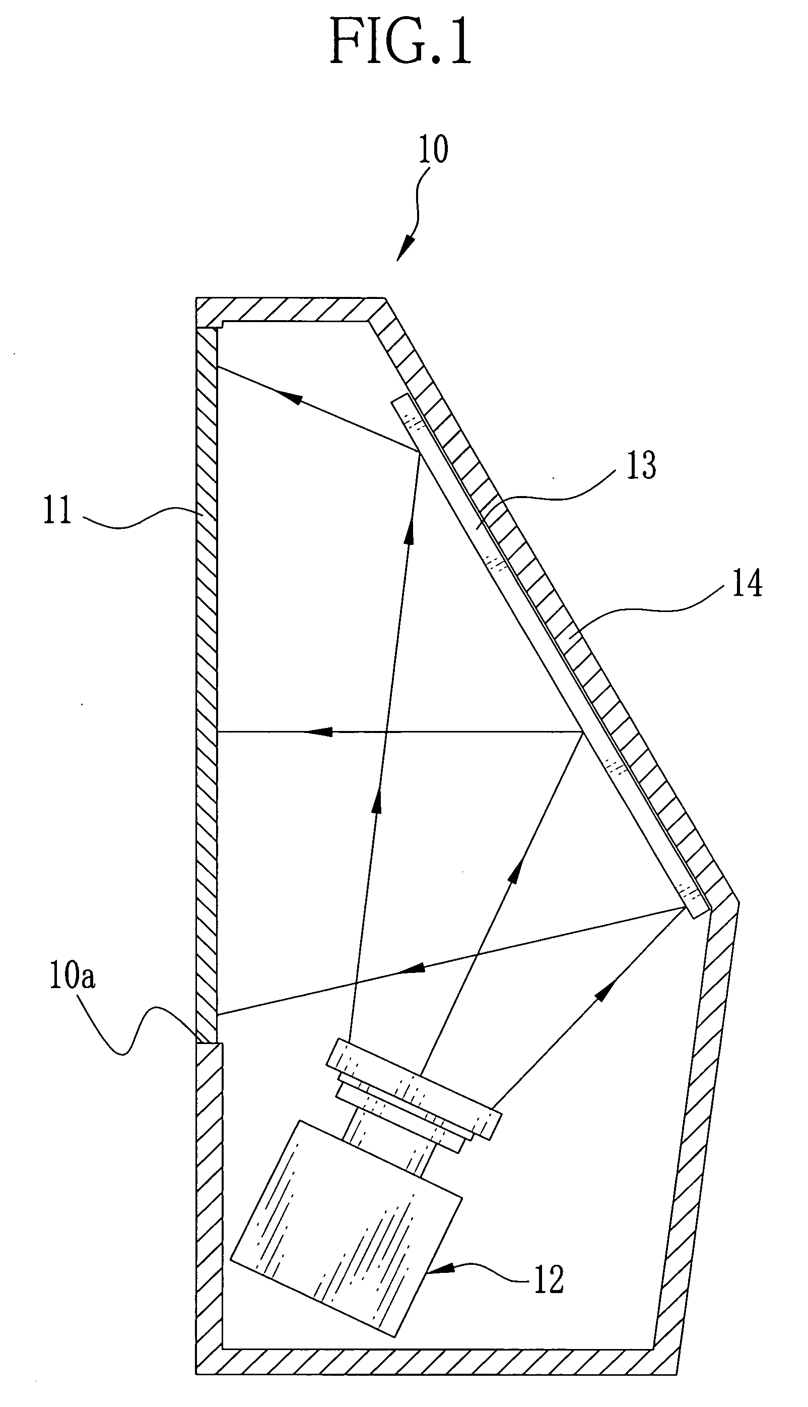
[0026] In FIG. 1, a rear projector 10 has a screen 11 of a transmissive type on which an image is projected, a projector unit 12 for outputting image light converted from illumination light, and a mirror 13 for reflecting the image light from the projector unit 12 toward the screen 11.

[0027] The projector unit 12 and the mirror 13 are provided inside a case 14, and the screen 11 is provided at an opening portion 10a of the case 14. The screen 11 has a horizontally long rectangular shape. The image light is projected from a rear side of the screen 11, and the image is viewed from its front side. The mirror 13 is a trapezoidal shape having an upper side longer than a lower side, and tilted with respect to the screen 11.

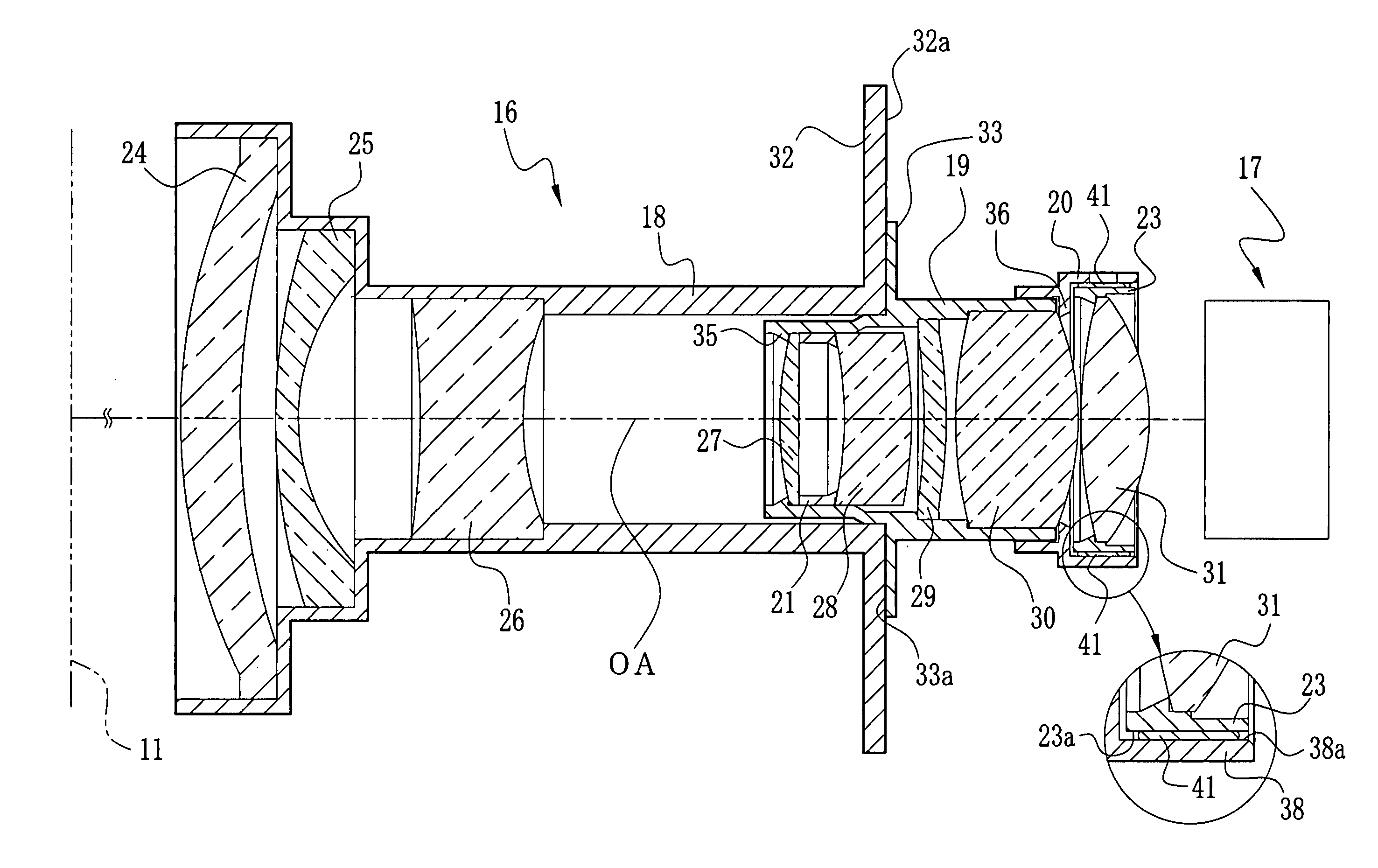
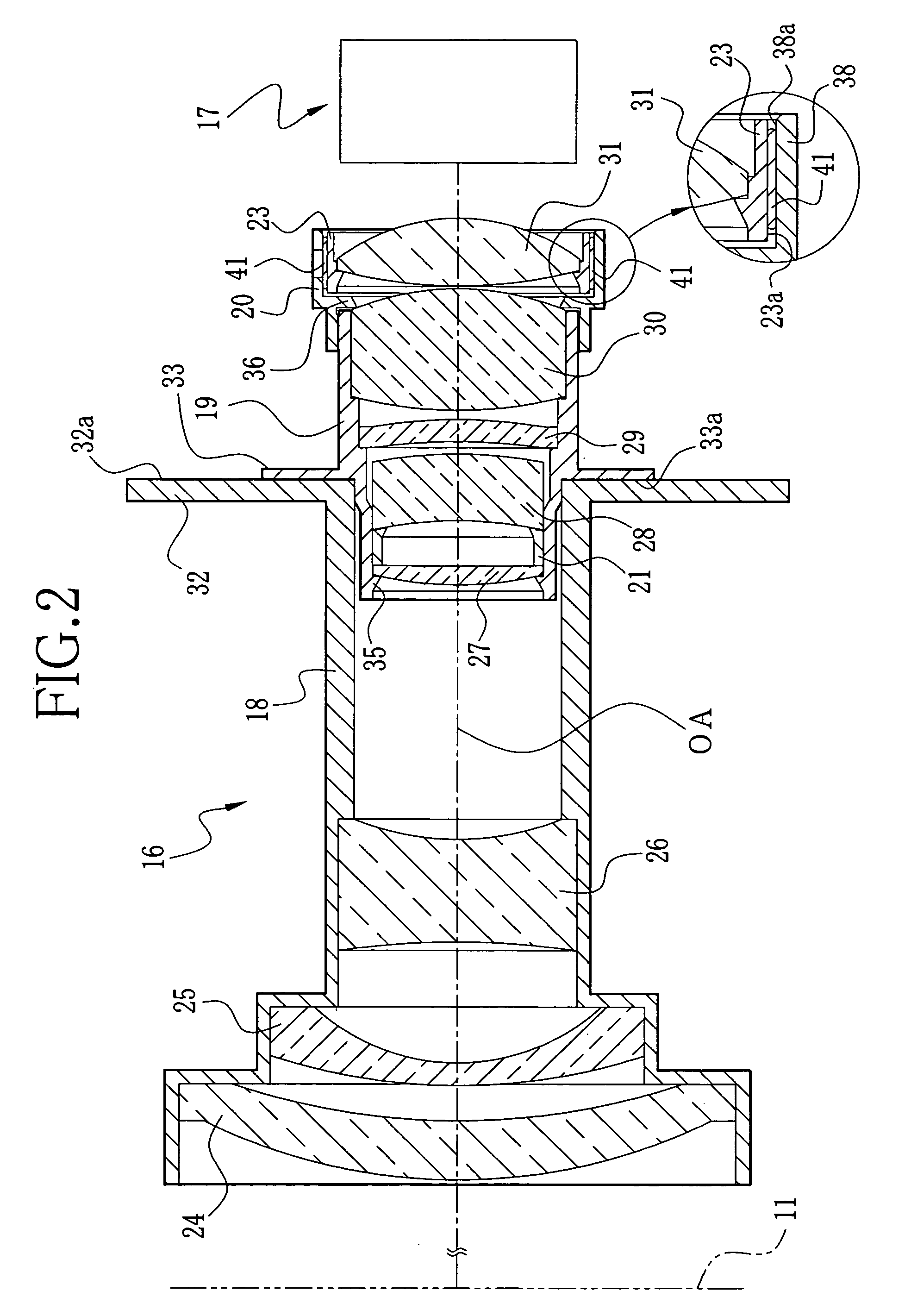
[0028] As shown in FIG. 2, the projector unit 12 includes a lens barrel 16 and an image light producer 17. The image light producer 17 is composed of a light source, a rod integrator and a liquid crystal display (LCD). The rod integrator uniforms energy distribution o...


PUM


Abstract

A third holding barrel is set to a stationary work holder, and a lens frame holding an eighth lens group is set to a movable work holder. The movable work holder is moved to insert the lens frame inside the third holding barrel. In this state, a chart image through the eighth lens group is projected on a screen. While checking the center and clarity of the projected image on the screen, position of the eighth lens group is adjusted. After the position adjustment, an adhesive is injected through openings of the third holding barrel by an injector, thereby fixing the lens frame to the third holding barrel.

Description

FIELD OF THE INVENTION [0001] The present invention relates to a lens barrel used in optical apparatuses such as a projector, a method for fixing a lens in the lens barrel, and a working apparatus for fixing the lens in the lens barrel. BACKGROUND OF THE INVENTION [0002] Optical systems used in optical apparatuses such as a projector, a digital camera, a film camera and the like are generally composed of a plurality of optical lenses. The optical lenses need to be fixed to their respective holding barrels such that an optical axis of each lens coincides. However, the optical lenses may be decentered when the holding barrels are processed with poor accuracy or the optical lenses are mounted in the holding barrels with poor precision. As a result, an optical performance of the whole optical system is lowered. [0003] In order to prevent the decentering of the optical lenses, in Japanese patent laid-open publication No. 8-327870, a first holding member which holds a first lens group is ...

Claims


Application Information

Patent Timeline
IPC IPC(8): G02B7/02
CPCG02B7/021G02B7/023G02B27/62
Inventor WATANABE, TAKASHI
Owner FUJI PHOTO OPTICAL CO LTD
Features
  • Generate Ideas
  • Intellectual Property
  • Life Sciences
  • Materials
  • Tech Scout
  • Unparalleled Data Quality
  • Higher Quality Content
  • 60% Fewer Hallucinations
Learn More