
Data packet retransmission and fec arrangement, and corresponding method

a data packet and data packet technology, applied in the field of data packet retransmission and forward error correction, can solve the problems of packet loss, packet loss, packet loss rate can amount to several percent, and achieve the effect of minimizing complexity

Inactive Publication Date: 2007-05-31
ALCATEL LUCENT SAS
View PDF26 Cites 28 Cited by
  • Summary
  • Abstract
  • Description
  • Claims
  • Application Information

AI Technical Summary

Benefits of technology

The data packet retransmission arrangement described in this patent text has several technical effects. Firstly, it uses a new retransmission strategy that limits the number of retransmission requests to a certain value, K. Secondly, it calculates N FEC packets based on the data packet and the data packets that are lost during transmission. Thirdly, it controls the retransmission buffer and the forward error correction device to either retransmit the data packet or transmit it together with the FEC packets. This arrangement helps to recover the lost data packet and minimize the impact of errors on the quality of experience. The latency and complexity of the arrangement can be controlled by adjusting K and N. The arrangement can be integrated into different types of network equipment and can be used in various applications.

Problems solved by technology

Due to noise, wire-bound and wireless physical layers are prone to bit errors that ultimately may translate in data packet loss.
When the packets that contain the video information are sent over an indoor wireless link, the packet loss rate can amount to several percents.
Also in a wired scenario where the video packets are for instance sent over an interleaved DSL line, the objective of 1 VDT cannot be guaranteed without proper protection of the video packets.
Retransmission techniques are efficient in terms of overhead—only data packets that are effectively lost or corrupted, are retransmitted—but the delay or latency associated with retransmission can be very large.
Concluding, although retransmission techniques are economical in sending overhead information on the link, the major bottleneck related to retransmission is the introduced latency which restricts the maximum amount of retransmissions.
A drawback of FEC techniques is that all packets are protected through FEC packets, also the packets that are received free of errors.
FEC techniques in other words introduce a permanent, additional overhead which can be too large in some cases.
Further, FEC techniques introduce delays as well, because collecting the packets upon which the FEC decoding has to be calculated takes time since these packets do not arrive instantly but arrive at the rate of the link.
In a wired scenario where for instance video packets are sent over a DSL loop operating at 20 Mbps, an overhead of more than 6% cannot be tolerated.
This restriction of low overhead and low latency (the zapping delay must stay below 150 ms) impedes the use of for instance powerful binary FEC codes to protect video packets sent over DSL lines.
Studies have shown that powerful binary codes on wireless links require a very high overhead, in excess of 60%, in order to comply with the viewers demand of less than 1 VDT.
Reed-Solomon codes are an alternative to their binary counterparts, requiring only 20 a 30% overhead on wireless links, but Reed-Solomon codes are less appealing because of their higher decoding complexity.
Summarizing, the latency introduced by conventional retransmission techniques is often too large to attain an acceptable quality of experience (e.g. a good zapping performance).
In particular on wireless links where the packet loss ratio can amount to several percents or on wire-bound links where the round-trip delay equals several tens of milliseconds, conventional retransmission techniques may not perform satisfactory.
FEC techniques on the other hand introduce overhead on top of the payload packets, and the overhead might be too large.
This is so because in order to reach a packet loss ratio that is low enough, powerful FEC codes may be required, introducing unacceptably high permanent overhead.

Method used


Image

  • Data packet retransmission and fec arrangement, and corresponding method
  • Data packet retransmission and fec arrangement, and corresponding method
  • Data packet retransmission and fec arrangement, and corresponding method

Examples


Embodiment Construction

)

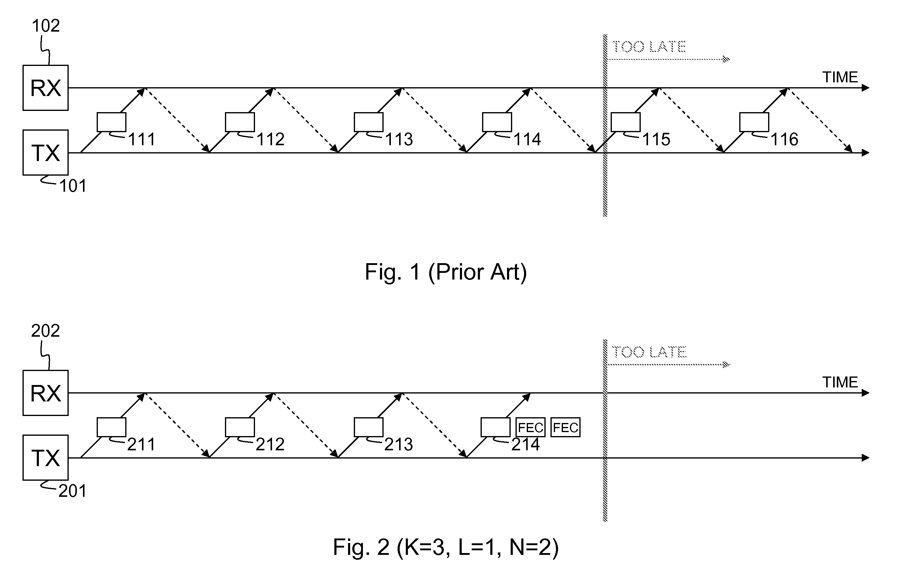
[0023] In FIG. 1 conventional retransmission over a DSL loop is illustrated. The round trip time, i.e. the time to send a video packet like 111 from the transmitter 101 integrated in the DSLAM to the receiver 102 integrated in the end user's video decoder plus the time to send a retransmission request back from the receiver 102 to the transmitter 101, is supposed to equal 35 milliseconds (note that this value is chosen by example: for interleaved DSL, values around 40 milliseconds are found in literature). The maximum acceptable delay in delivering video packets is assumed to be 150 milliseconds for zapping purposes. Packets that are delivered with a delay exceeding 150 milliseconds in other words arrive too late and cannot be used anymore for display to the viewer. The video packet 111 in FIG. 1 is supposed to be corrupted or lost on the DSL line. In response to the retransmission request, represented by the dashed arrow in FIG. 1, the transmitter 101 re-sends a copy of the video ...


PUM


Abstract

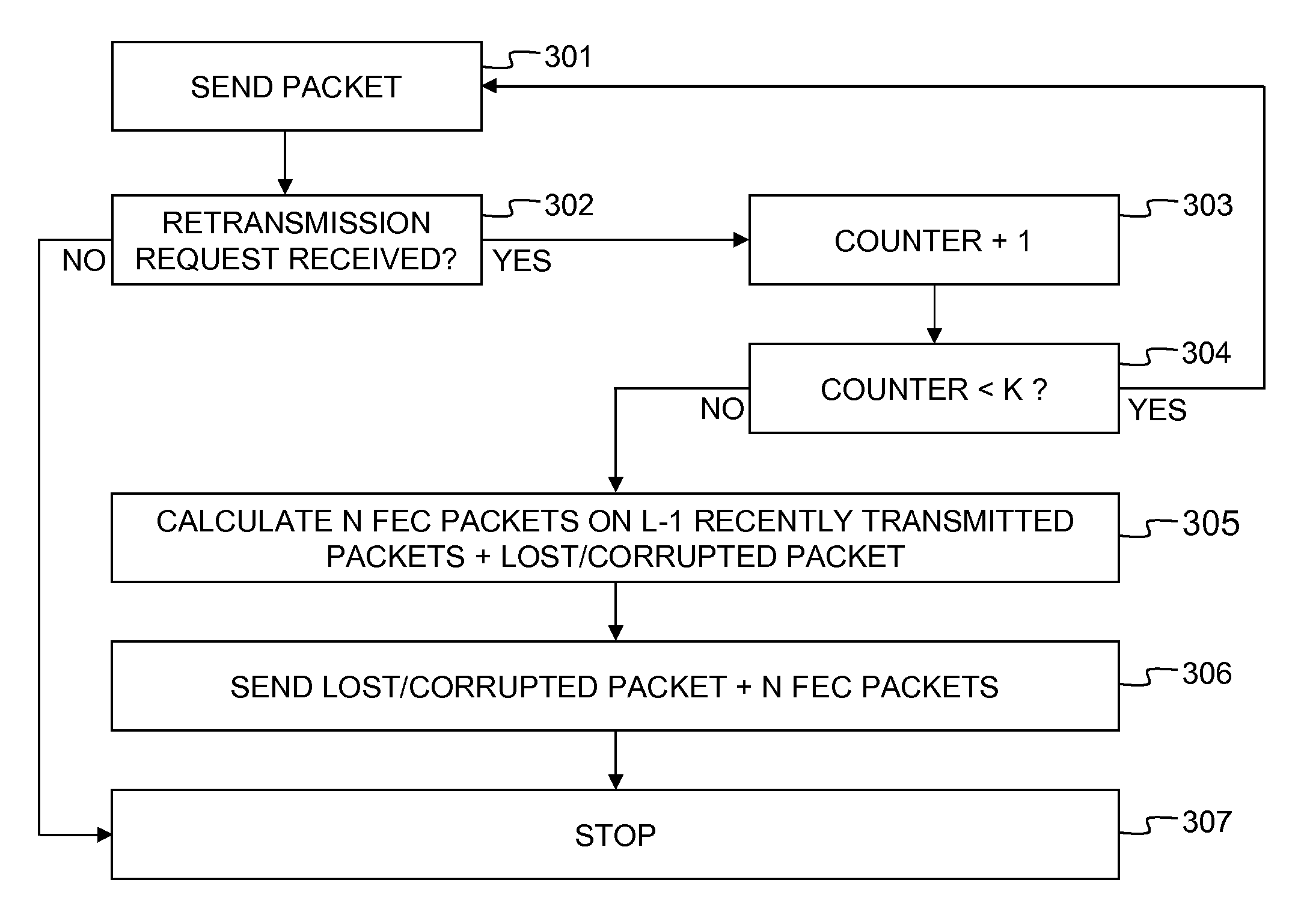
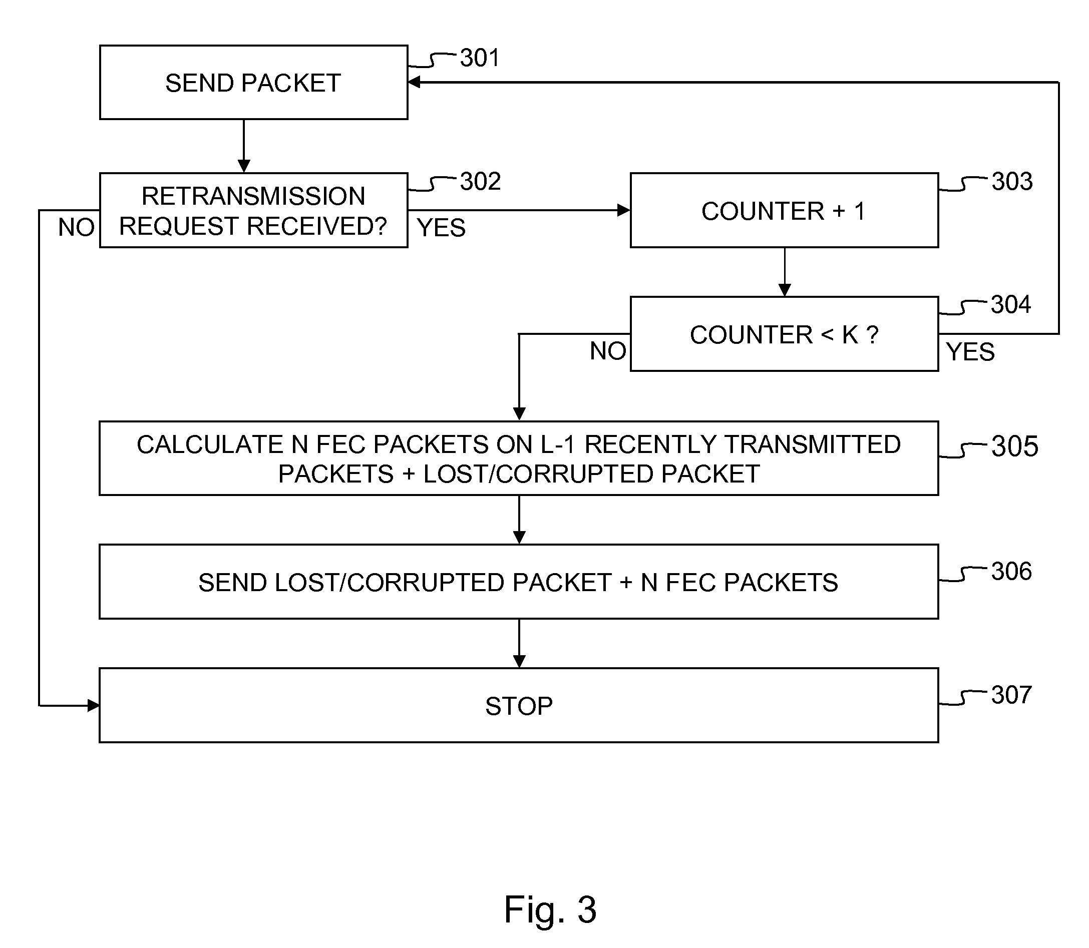
The invention concerns a data packet retransmission arrangement having a retransmission buffer, a counter, a forward error correction device and control logic. The retransmission buffer stores recently transmitted data packets. The counter keeps track of the number of retransmission requests received for a data packet (211). If this number is below a first integer value K, the data packet is retransmitted (212, 213). If this number is equal to or above the first integer value K, the forward error correction device calculates N forward error correction packets on L-1 recently transmitted data packets plus the data packet to be retransmitted (211), N being a second integer value equal to or larger than zero, and L being a third integer value equal to or larger than 1. In the latter case, the data packet is retransmitted together with the N forward error correction packets (214).

Description

FIELD OF THE INVENTION [0001] The present invention generally relates to data packet retransmission and Forward Error Correction (FEC) for protection of data packet transmissions against packet loss or packet corruption due to noise on wire-bound or wireless links, like for instance a Digital Subscriber Line (DSL) or a Wireless Local Area Network (WLAN) link. Data packet in the context of the current patent application means any fixed length or variable length packet conveying information of whatever nature or service (voice, video, TV, Internet, gaming, multimedia, data files, . . . ) over links of a communication network. BACKGROUND OF THE INVENTION [0002] Due to noise, wire-bound and wireless physical layers are prone to bit errors that ultimately may translate in data packet loss. At the link layer, solutions exist for protection against bit errors on the physical layer. In general, two main techniques exist for error protection in packet based networks: retransmission and Forwa...

Claims


Application Information

Patent Timeline
Patent Type & Authority Applications(United States)
IPC IPC(8): H04L12/56
CPCH04L1/004H04L1/1812
Inventor DEGRANDE, NATALIEDELA VALLEE, PALOMADE VLEESCHAUWER, DANNY
Owner ALCATEL LUCENT SAS
Learn More