
First-order loudspeaker crossover network

a crossover network and loudspeaker technology, applied in the direction of transducer details, electrical transducers, electrical apparatus, etc., can solve the problems of high cost of capacitors and inductors used in crossover networks, the inability of first-order networks to provide, and the significant increase in the cost of loudspeaker systems by additional components

Inactive Publication Date: 2007-05-31
THOMSON LICENSING SA
View PDF2 Cites 14 Cited by
  • Summary
  • Abstract
  • Description
  • Claims
  • Application Information

AI Technical Summary

Benefits of technology

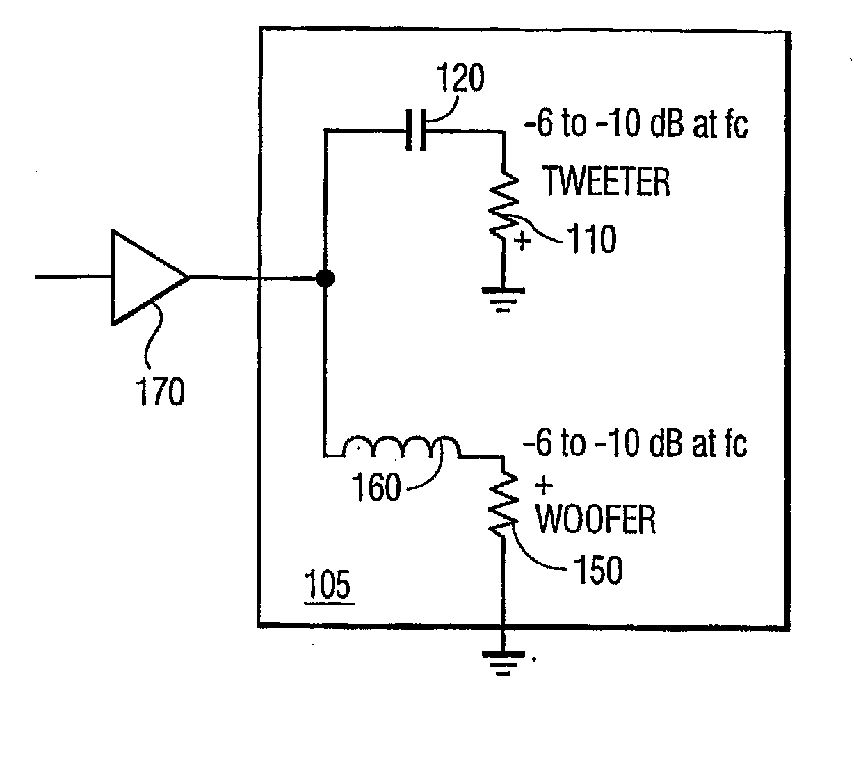
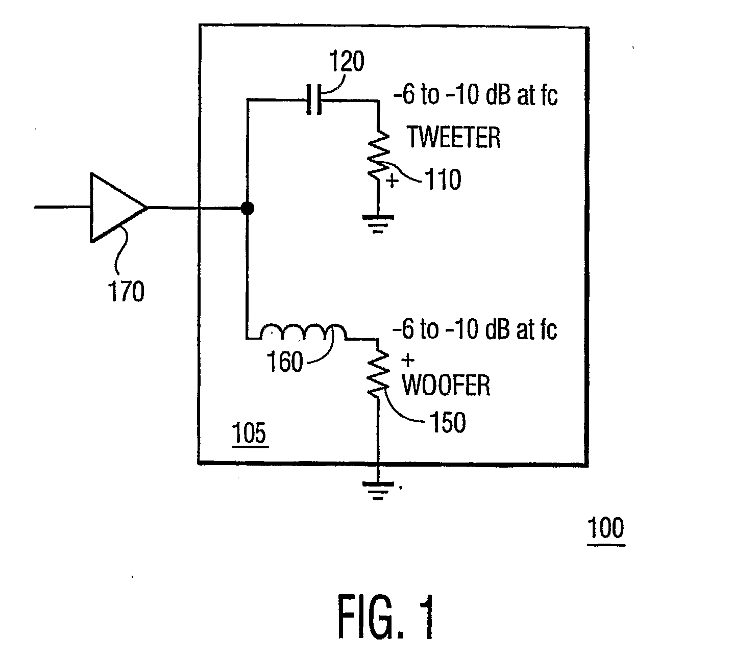
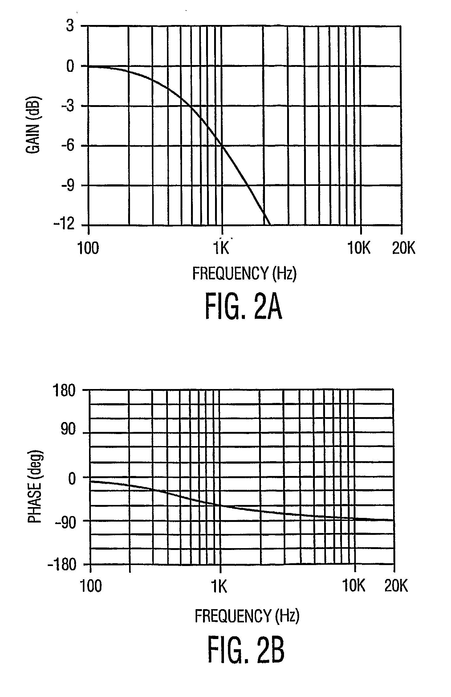
[0007] In one embodiment, the low-pass filter is formed by an inductor coupled in series to the first loudspeaker in a first polarity, and the high-pass filter is formed by a capacitor coupled to the second loudspeaker in a second polarity. The impedance of the inductor and the capacitor is selected such that the phase difference is no greater than 60 degrees. Preferably, the phase difference should be about 40 degrees to create a near in-phase effect.

Problems solved by technology

As such, such a first-order network cannot provide the following benefits of an in-phase crossover network: smoother frequency response due to increased stop-band rejection, and improved polar behavior (lobing).
These additional components significantly increase the cost of a loudspeaker system because capacitors and inductors used in a crossover network are generally expensive due to their size, capacity, and power requirements.

Method used


Image

  • First-order loudspeaker crossover network
  • First-order loudspeaker crossover network
  • First-order loudspeaker crossover network

Examples


Embodiment Construction

[0020]FIG. 1 illustrates a two-way loudspeaker system 100 using a first-order crossover network 105 according to the principles of the invention. The two-way loudspeaker system 100 includes a tweeter 110, represented by a resistor in FIG. 1, and a woofer 150, also represented by a resistor in FIG. 1. Each of the tweeter 110 and the woofer 150 has a positive terminal (shown as + in FIG. 1) and a negative terminal (opposite to the terminal marked as “+” in FIG. 1). Input audio signals to the crossover network 105 may be amplified by an amplifier 170. The crossover network 105 includes a capacitor 120 coupled in series to the tweeter 110 to form a high-pass filter for providing high frequency band input signals to the tweeter 110, and an inductor 160 coupled in series to the woofer 150 to form a low-pass filter for providing low frequency band input signals to the woofer 150. The inductor 160 is coupled to the woofer 150 in a first polarity and the capacitor 120 is coupled to the tweet...


PUM


Abstract

A first-order crossover network having low-pass and high-pass filters to respectively drive first and second loudspeakers in a loudspeaker system is designed such that the phase difference at a crossover frequency between output signals of the first and second loudspeakers is no greater than 60 degrees, so that the output signals are at least partially in phase. Preferably, the phase difference should be about 40 degrees to create a near in-phase effect. The polarity in which the first loudspeaker is coupled to the first-order crossover network is an inverse of the polarity in which the second loudspeaker is coupled to the crossover network. Optionally, the input signals can be equalized to flatten the magnitude responses of the crossover network.

Description

TECHNICAL FIELD OF INVENTION [0001] This invention relates to the field of loudspeaker crossover networks, and, more particularly, to a first order loudspeaker crossover network having some advantages of a second order loudspeaker crossover network. BACKGROUND OF THE INVENTION [0002] A crossover network is used to separate input audio signals into multiple frequency bands in a multi-way loudspeaker system, each band feeding a different loudspeaker best suited for the associated frequency band. A frequency that separates one band from another band is called the crossover frequency of these two bands. For example, in a two-way loudspeaker system to be discussed below, the low frequency and high frequency bands are directed to a woofer and a tweeter, respectively, and the crossover frequency is the frequency where the lower frequency and high frequency bands divide. [0003] In a first-order crossover network, such a first-order Butterworth network, a capacitor is coupled in series to a ...

Claims


Application Information

Patent Timeline
IPC IPC(8): H03G5/00H04R3/14
CPCH04R3/14
Inventor RUMREICH, MARK FRANCIS
Owner THOMSON LICENSING SA
Learn More