
Face detection in digital images

a technology of face detection and digital images, applied in image data processing, television systems, instruments, etc., can solve the problems of much more time-consuming operation, and achieve the effect of reducing computational complexity and overall efficiency

Inactive Publication Date: 2007-05-31
PIXOLOGY SOFTWARE
View PDF12 Cites 29 Cited by
  • Summary
  • Abstract
  • Description
  • Claims
  • Application Information

AI Technical Summary

Benefits of technology

[0014] A considerable time saving can be obtained by reducing the number of pixels which need to be searched. The image size is reduced by ignoring most of the pixels in the image, and performing all subsequent operations on just a selection of these pixels. This is distinct from the process of compressing an image to reduce its size, which is a much more time consuming operation. Since a face will always occupy a significant number of pixels, sufficient information is contained in just a small selection of these pixels.
[0018] The use of a map enables the colour space data of pixels in the image to be replaced by map elements containing more focussed information, speeding up subsequent operations in detecting regions corresponding to a face. In preferred embodiments the map is produced from the sampled image described above. In order to keep the total data held by the map as small as possible, the map preferably contains 256×256 elements or fewer, each element being represented by one byte of information (i.e. a value between 0 and 255).
[0019] The map is preferably populated from a look-up table. This enables the value of each map element to be determined quickly. As an example, the look-up table may be a matrix of 64×64×64 bytes, with the inputs being the R, G and B values of each pixel scaled down by a factor of 4.
[0024] Preferably the categories of some or all of the elements in a skin tone region are merged on the basis of the categories of all the elements in that skin tone region. This step reduces the number of different categories of elements, decreasing complexity in subsequent steps.

Problems solved by technology

This is distinct from the process of compressing an image to reduce its size, which is a much more time consuming operation.

Method used


Image

  • Face detection in digital images
  • Face detection in digital images
  • Face detection in digital images

Examples


Embodiment Construction

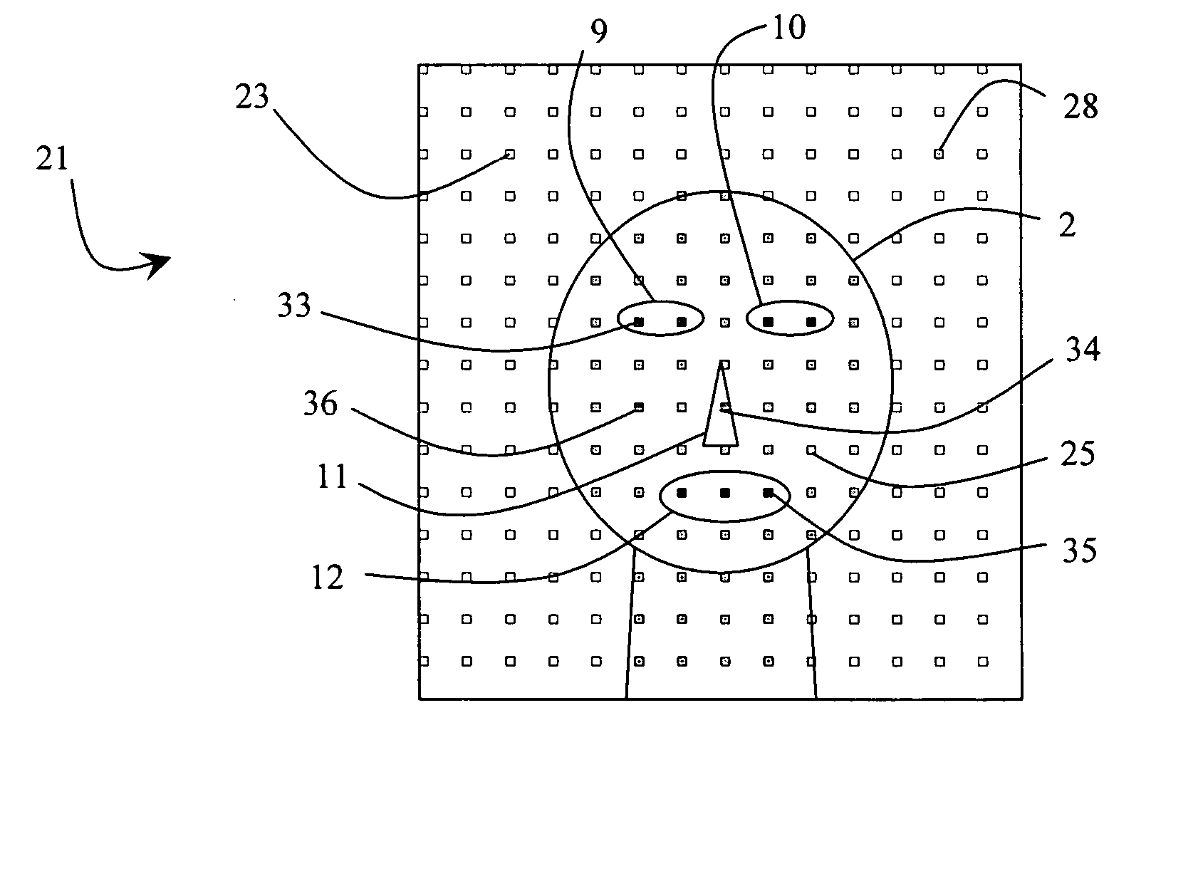
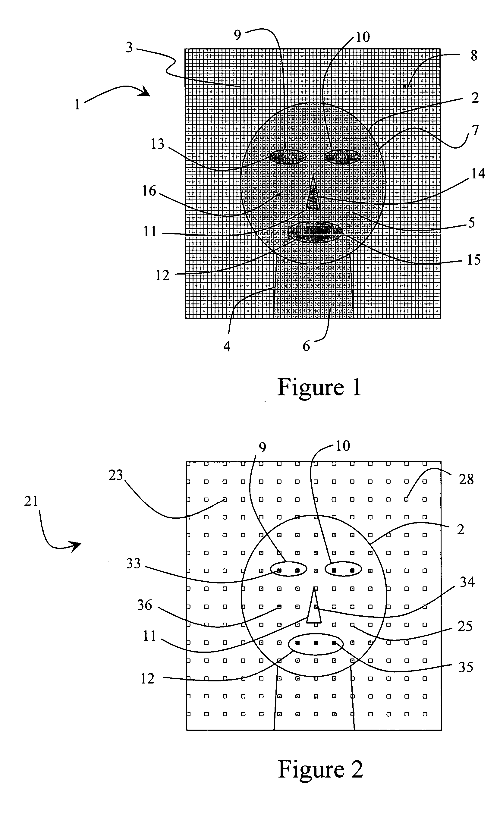
[0057]FIG. 1 is a schematic representation of an exemplary digital image 1 of a face 2. The image 1 is formed of 70×75 pixels 3. It will be understood that, in practice, digital images have far more pixels than shown in FIG. 1: typical images range from 160×240 pixels upwards to 12 Megapixels (e.g. 3000×4000 pixels) or even more. However, the principle of the image can be seen from FIG. 1.

[0058] As can be seen from FIG. 1, the image includes a face region 2 and neck region 4. The pixels 5, 6 within the face region and neck regions are the colour of human skin, or “skin tone” pixels. The face and neck thus together form a “skin tone region”7. The range of colours (or RGB values) of skin tone pixels varies from light to dark so as to include different skin types and lighting conditions, but is still small compared to the full colour range possible. Due to the need to cover all (or most) skin types, many non-skin pixels also fall within this range—examples include those found on light...


PUM


Abstract

A method of detecting a face in a digital image comprises generating a map from the image, the map having a plurality of elements each corresponding to a pixel of the image, and searching the map for regions of elements corresponding to regions of pixels in the image exhibiting characteristics of a face. The map may have elements corresponding only to a small proportion of the pixels in the original image. Validation of regions exhibiting the characteristics of a face may include matching against templates. Once the location and size of a face has been identified it may be passed to the control system of a camera to enable the camera to focus on that face and / or select a suitable photograph exposure to optimise the exposure of that face.

Description

FIELD OF THE INVENTION [0001] The present invention relates to face detection in digital images. In particular, although not exclusively, the invention relates to a system for identifying a face to enable a camera to focus on that face and / or control the exposure of a photograph to optimise the exposure of the face. BACKGROUND TO THE INVENTION [0002] A large proportion of photographs, especially those taken by recreational photographers, include people. In such situations, it is important that the camera focuses on the faces in the composition rather than on anywhere else in the picture. For some portrait photography a wide aperture is deliberately used to ensure that the face is in focus but all the surroundings are blurred. [0003] Ensuring that the face is in focus can be problematic, especially in cases where the face is not in the centre of the picture. Many cameras automatically focus on a point in the centre of the field of view. If this point is located at a different distanc...

Claims


Application Information

Patent Timeline
IPC IPC(8): G06K9/00
CPCG06K9/00234H04N5/23212H04N5/235G06V40/162H04N23/675H04N23/61H04N23/70G06T7/90G06T7/60
Inventor MAOR, RON
Owner PIXOLOGY SOFTWARE
Learn More