Motor

Active Publication Date: 2007-05-31
NIDEC CORP
View PDF6 Cites 20 Cited by
  • Summary
  • Abstract
  • Description
  • Claims
  • Application Information

AI Technical Summary

Benefits of technology

[0006] In order to overcome the problems described above, preferred embodiments of the present invention provide a motor havin

Problems solved by technology

In such a motor, however, a large electric current flows into a coil of an armature of the motor, and the coil generates considerable heat.
The heat may substantially compromise reliability and endurance of the m

Method used


Image

  • Motor
  • Motor
  • Motor

Examples


first preferred embodiment

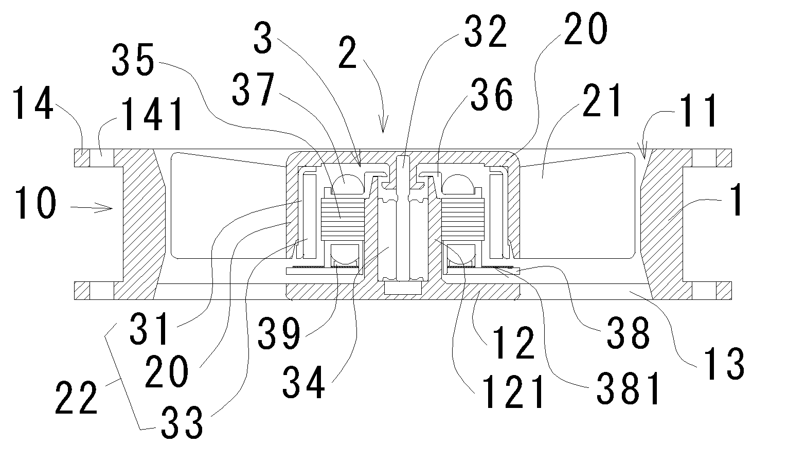
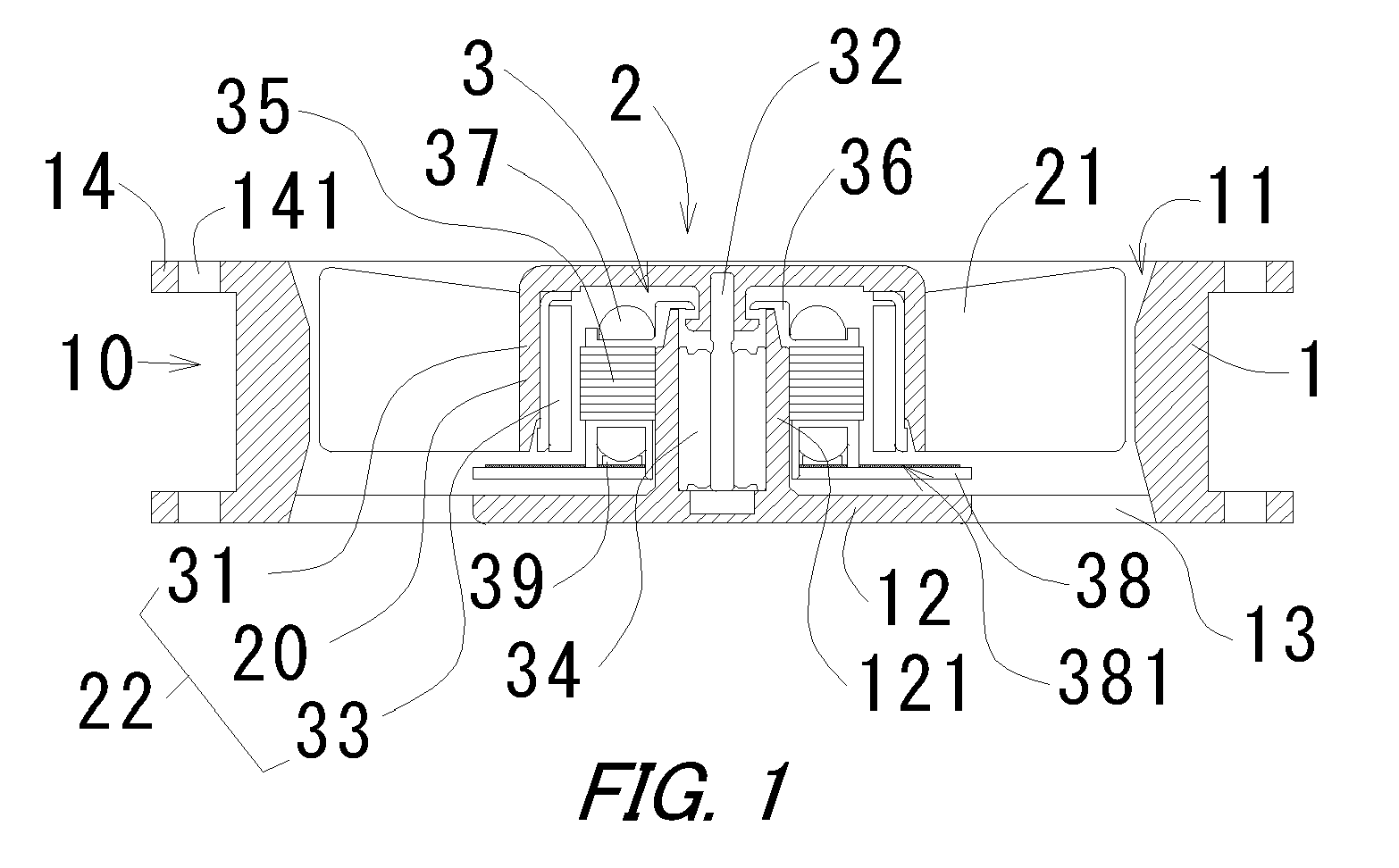
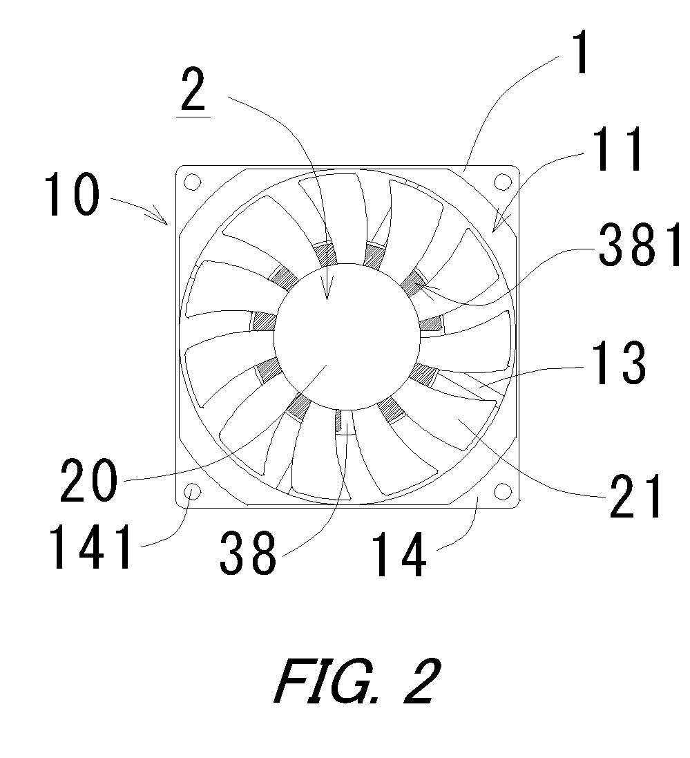
[0021] Referring to FIGS. 1 and 2, a configuration of the fan 10 according to a first preferred embodiment of the present invention will be described. A fan 10 includes an impeller 2 having a plurality of impeller blades 21. The impeller 2 is rotatably driven with electricity supplied to the fan 10. The impeller 2 includes a substantially cup-shaped impeller cup 20, and a plurality of impeller blades 21 are arranged around an outer circumferential surface of the impeller cup 20. The fan 10 includes a shaft 32, of which an upper tip portion is mounted to a substantially center portion of the impeller 2 in a fixed manner.

[0022] The fan 10 includes a frame 12 having a bearing housing 121 at a middle portion thereof. The bearing housing 121 has a substantially cylindrical shape with a base connected to the frame 12. A radial bearing 34 is press-fitted and supported within the bearing housing 121. The radial bearing 34 includes a through hole extending in the axial direction at a middle...

second preferred embodiment

[0035] Referring to FIGS. 6 to 10, a second preferred embodiment of the present invention will be described in detail. In the description that follows, similar configurations described in the first preferred embodiment are labeled with the same reference numerals in the explanation that follows. In the second preferred embodiment of the present invention, the motor is used for a fan.

[0036] A fan 100 includes an impeller 2a having a plurality of impeller blades 21a. The impeller 2a is rotatably driven when electricity is supplied to the fan 100. As shown in FIGS. 6 and 7, the impeller 2a includes a substantially cup-shaped impeller cup 20a. A plurality of impeller blades 21a extending axially are arranged in a circular manner radially outside of the impeller cup 20a. The impeller blades 21a arranged in a circular manner are connected with a circular impeller-supporting portion 23a in a fixed manner. The impeller supporting portion 23a is connected to the impeller cup 20a with a plur...


PUM


Abstract

A motor includes a heat dissipating structure. The motor may be used for a fan and includes on an upper surface of a circuit board a heat dissipating layer. The heat dissipating layer has a high thermal conductivity. The fan also includes a coil provided on the teeth of a stator core. The heat dissipating layer and the coil axially face each other, and thermal conductive members are arranged therebetween. An outer dimension of the circuit board is greater than that of an impeller cup so that a radially outward portion of the circuit board protrudes radially outwardly from the impeller cup. The heat generated by the coil is transferred to the heat dissipating layer via the thermal conductive members. Therefore, the heat is dissipated from a wide area, which efficiently dissipates heat from the fan. In addition, since the circuit board and the heat dissipating layer protrude radially into an air-flow generated by an impeller, the heat transferred to the heat dissipating layer is actively dissipated.

Description

BACKGROUND OF THE INVENTION [0001] 1. Field of the Invention [0002] The present invention generally relates to a motor equipped with a coil, more particularly, relates to a heat dissipating structure of the motor to dissipate heat generated by the armature. [0003] 2. Description of the Related Art [0004] With numerous fans and drive motors for heat dissipation, disk drives, and like applications being installed in electronic devices, high speed motor operation is being demanded, in part because the demand for high speed data transfer and high heat dissipating capacity is increasing. A motor which rotates at a high speed is one answer to this need. In such a motor, however, a large electric current flows into a coil of an armature of the motor, and the coil generates considerable heat. The heat may substantially compromise reliability and endurance of the motor since a copper wire used for the coil has a temperature limit and the generated heat influences bearing life. [0005] A motor...

Claims


Application Information

Patent Timeline
IPC IPC(8): F04B17/00
CPCF04D25/082F04D25/0633F04D29/5806
Inventor SUGIYAMA, TOMOTSUGUTAKEMOTO, SHINJIYASUMURA, TSUYOSHI
Owner NIDEC CORP
Why Eureka
Try Eureka