
Screw locking mechanism and method

a locking mechanism and screw technology, applied in the field of screw locking mechanism and method, can solve the problems of affecting the recovery of vertebrae, and reducing the strength of vertebrae, so as to facilitate the retention of said first

Active Publication Date: 2007-05-31
X SPINE SYST
View PDF54 Cites 49 Cited by
  • Summary
  • Abstract
  • Description
  • Claims
  • Application Information

AI Technical Summary

Benefits of technology

[0009] In one aspect, this invention comprises a plate system for stabilizing various bony structures, said plate system comprising a first screw having a first head, said first head comprising a wall having a first portion and a second portion; and a second screw having a second head having a second wall; said first portion being dimensioned such that when said first portion is situated opposite said second wall, said second head may be rotated to screw said second screw into said spinal bone of said spinal column, said first portion of said first screw may thereafter be rotated so that said second portion may engage said second wall in order to facilitate retaining said first and second screws in a tightened position.

Problems solved by technology

Over time these disks can dry out and become flattened, causing the vertebrae to lose height and its healthy resilience.
The degeneration of the disks allow the vertebrae get closer together and cause nerve irritation, which usually stems from a ruptured disc, bone spurs or stenosis.
Vertebral motion (neck movement) results in chronic pain.
One of the problems associated with the fusion of cervical vertebrae is the tendency of the screws or other fasteners to loosen over time.
As the fasteners or screws loosen the plate is not able to support or maintain the proper orientation of the vertebrae.
The plate and other associated implants, which are no longer secure, can cause irritation and even trauma to local tissue structures.

Method used


Image

  • Screw locking mechanism and method
  • Screw locking mechanism and method
  • Screw locking mechanism and method

Examples


embodiment 1

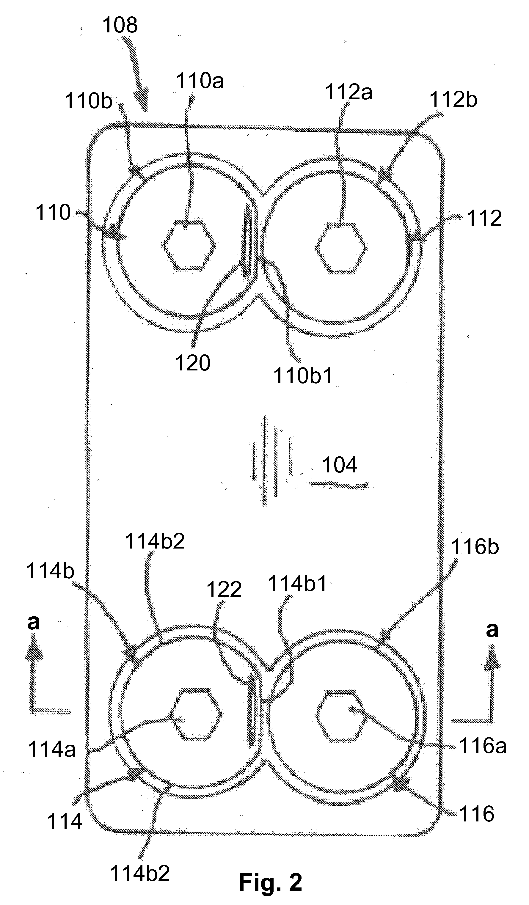
[0030] 2. The medical screw as recited in embodiment 1 wherein said head comprises: a large radius portion and a small radius portion; said small radius portion defining said first portion and permitting said adjacent screw to be turned when said small radius portion is situated in opposed relationship to said adjacent screw.

[0031] 3. The medical screw as recited in embodiment 1 wherein said medical screw is titanium.

[0032] 4. A locking screw for use in a prosthetic implant procedure, comprising: a threaded portion; a head portion integral with said threaded portion; and said head portion comprising a non-camming area and a camming area.

embodiment 4

[0033] 5. The locking screw as recited in embodiment 4 wherein said head portion comprises indicia associated with said non-camming area.

[0034] 6. A prosthetic implant plate system comprising: a plate member; and a lock system for preventing withdrawal of at least one screw after said at least one screw is received in an opening in the plate member and screwed into a spinal bone.

embodiment 6

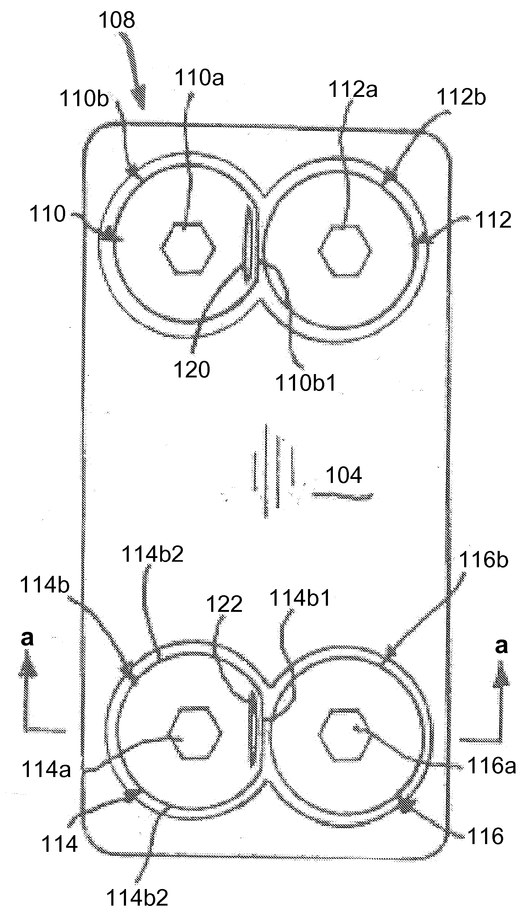
[0035] 7. The prosthetic implant plate system as recited in embodiment 6 wherein said lock system comprises an elongated resilient member integrally formed in said plate member; said resilient member retaining said at least one screw in a secured position in said spinal column.

[0036] 8. The prosthetic implant plate system as recited in embodiment 6 wherein said resilient member is biased radially towards a head of said at least one screw such that a portion of said resilient member becomes situated over a head of said at least one screw

[0037] 9. The prosthetic implant plate system as recited in embodiment 6 wherein said plate member is titanium.

[0038] 10. The prosthetic implant plate system as recited in embodiment 6, wherein said lock system comprises: at least one pair of screws situated adjacent each other; at least one of said at least one pair of adjacent screws comprising a camming head for engaging a head of the other of said at least one pair of screws to facilitate retain...


PUM

PropertyMeasurementUnit
flat areaaaaaaaaaaa
radiusaaaaaaaaaa
sizeaaaaaaaaaa

Abstract

This invention relates to a bony fixation system and method for use as a prosthetic implant. The system and method includes a plate dimensioned to be situated between adjacent bony structures, such as adjacent vertebrae. Screws are provided in one embodiment and are dimensioned or configured to be inserted into a bony structure and to lock against each other to retain the screws and consequently secure the plate in place against the bony structure.

Description

RELATED APPLICATION DATA [0001] This application is a continuation-in-part of U.S. patent application Ser. No. 10 / 858,629, filed Jun. 2, 2004, which is a continuation-in-part of U.S. patent application Ser. No. 10 / 675,361 filed Sep. 30, 2003.FIELD OF THE INVENTION [0002] The present invention relates to orthopedic implants and to methods of treating bony defects, and more particularly to plate systems used for fusing bony structures. BACKGROUND [0003] The spine of most human adults consists of 24 connected bones called vertebrae. The cervical vertebrae begin at the base of the skull. Seven vertebrae make up the cervical spine, which are abbreviated C1, C2, C3, C4, C5, C6 and C7. The cervical vertebrae are smaller in size compared to other spinal vertebrae. The purpose of the cervical spine is to contain and protect the spinal cord, support the skull, and enable a wide range of head movement. The vertebrae allow the head to rotate side to side, bend forward and backward. [0004] Frequ...

Claims


Application Information

Patent Timeline
Patent Type & Authority Applications(United States)
IPC IPC(8): A61F2/30
CPCA61B17/7059A61B17/8042A61B17/8047A61B17/8052A61B17/8605A61F2/30744A61F2/44A61F2/4465A61F2/447A61F2002/2835A61F2002/30062A61F2002/30131A61F2002/30383A61F2002/30385A61F2002/30398A61F2002/30439A61F2002/305A61F2002/30505A61F2002/30507A61F2002/30517A61F2002/30576A61F2002/30578A61F2002/30604A61F2002/30616A61F2002/30784A61F2002/30785A61F2002/30794A61F2002/30904A61F2002/4475A61F2002/449A61F2210/0004A61F2220/0025A61F2220/0041A61F2230/0013A61F2310/00017A61F2310/00023A61F2310/00161A61F2002/30433A61F2002/30593A61F2002/3079
Inventor KIRSCHMAN, DAVID LOUIS
Owner X SPINE SYST
Features
  • Generate Ideas
  • Intellectual Property
  • Life Sciences
  • Materials
  • Tech Scout
  • Unparalleled Data Quality
  • Higher Quality Content
  • 60% Fewer Hallucinations
Learn More