Supercharge Your Innovation With Domain-Expert AI Agents!

Programmed material consolidation methods employing machine vision

a technology of machine vision and material consolidation, applied in the field of three-dimensional (3d) printing, can solve the problems of significantly slower processing time for immersion-type stereolithography systems, lack of image sensors for ensuring, and inconvenient use of 3-d printing systems

Inactive Publication Date: 2007-05-31
FARNWORTH WARREN M +1
View PDF59 Cites 10 Cited by
  • Summary
  • Abstract
  • Description
  • Claims
  • Application Information

AI Technical Summary

Benefits of technology

[0014] The machine vision system of the present invention enables the precise deposition of flowable material in a desired location on or over the substrate. The machine vision system includes an optical detection element, such as a camera, as well as a controller or processing element, such as a computer processor or a collection of computer processors, associated with the optical detection element. The optical detection element may be positioned in a fixed location relative to the substrate, mounted on the dispense element, enabling movement thereof over a substantial portion of the substrate, or moveable independently of the dispense element over a substantial portion of the substrate. The optical detection element of the machine vision system is useful for identifying the locations of recognizable features, including, without limitation, features on a substrate and features, such as fiducial marks or other objects at a fabrication site, and features that have been formed on or over the substrate or at the fabrication site.

Problems solved by technology

Accordingly, conventional 3-D printing systems lack image sensors for ensuring that structures are fabricated at specific, desired locations.
While the above-referenced Farnworth patent and patent application disclose forming a variety of different structures on a semiconductor assembly, the disclosed immersion-type stereolithography processes require the use of an excess amount of expensive photopolymer material.
Furthermore, the processing time using immersion-type stereolithography systems is significantly slower than the processing time for a 3-D printing system, such as the aforementioned Objet systems.

Method used


Image

  • Programmed material consolidation methods employing machine vision
  • Programmed material consolidation methods employing machine vision
  • Programmed material consolidation methods employing machine vision

Examples


Embodiment Construction

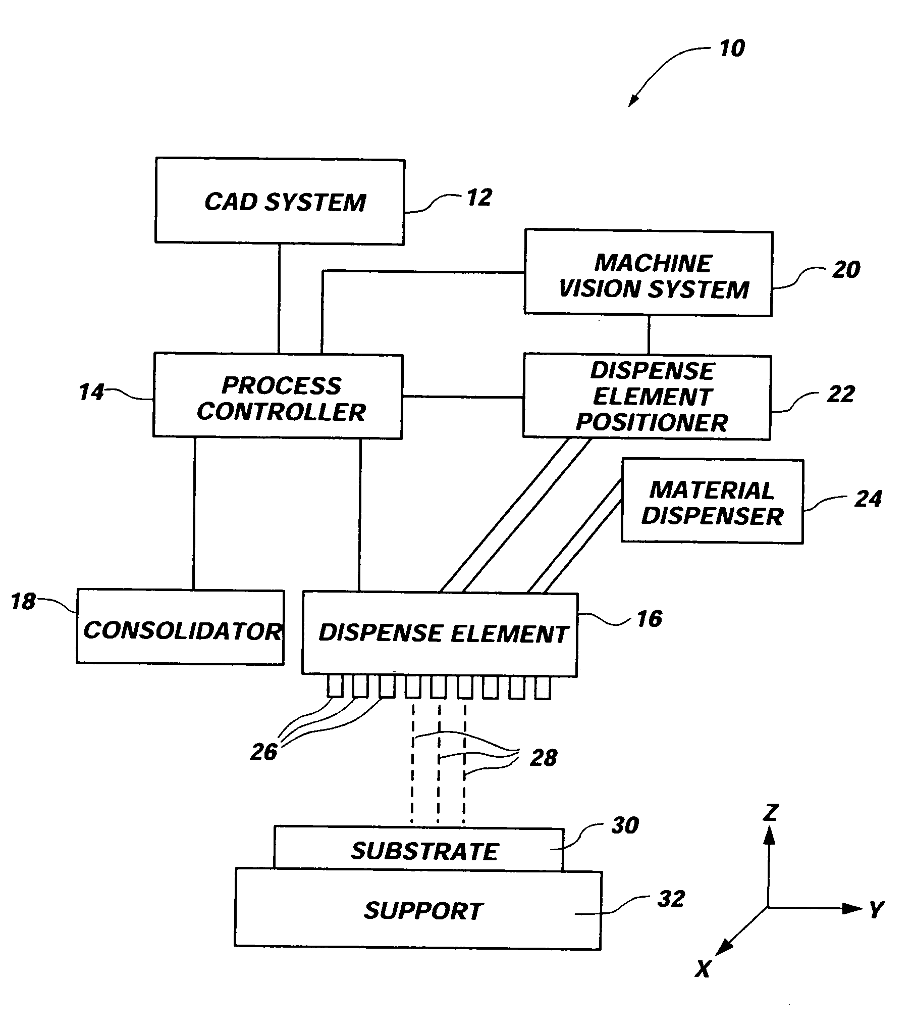
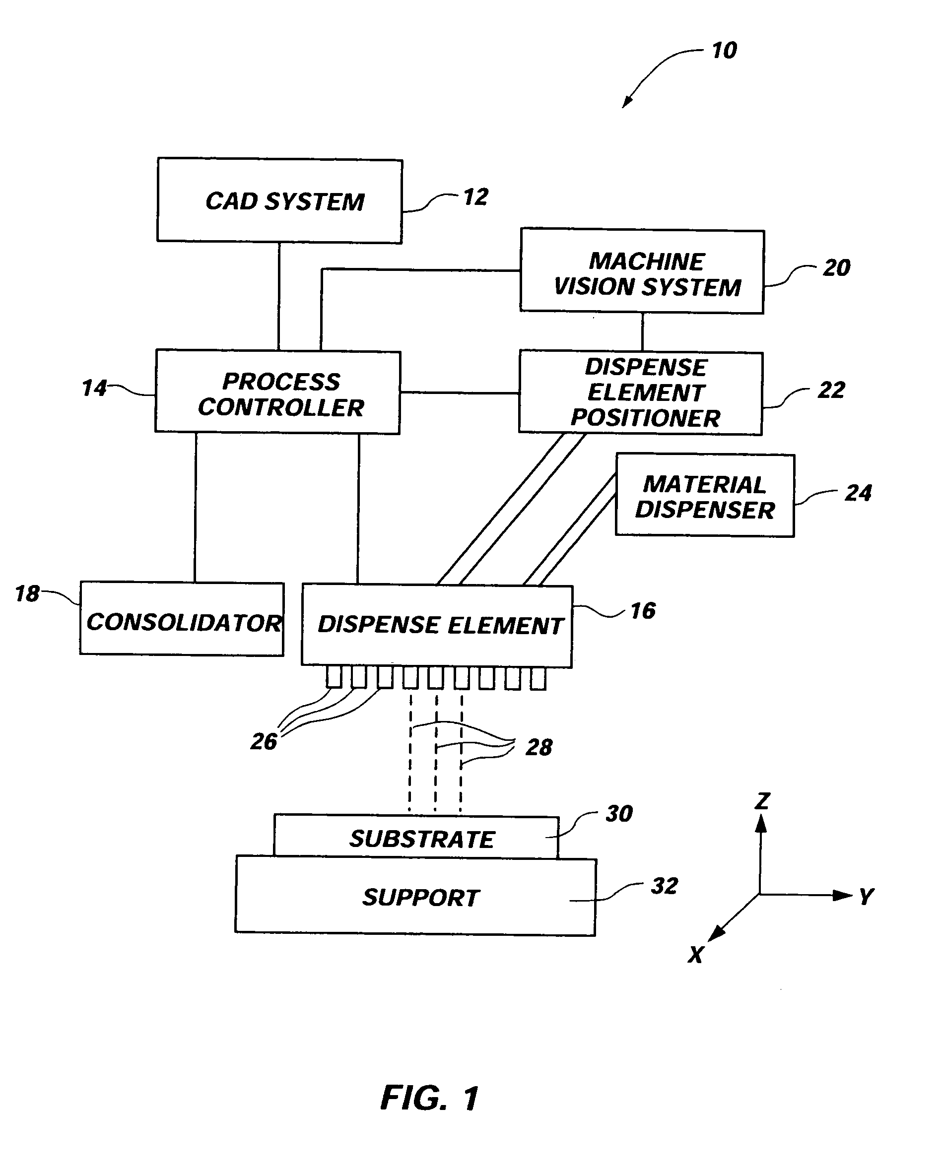
[0026]FIG. 1 illustrates a block diagram of an exemplary programmable material consolidation system 10 for 3-D printing objects that employs a machine vision system 20 enabling the accurate deposition of flowable material 28 for forming a variety of different structures. One suitable programmable material consolidation system 10 is the commercially available Eden 330® manufactured by Objet Geometries Ltd. of Rehovot, Israel, that is modified to include a machine vision system 20 in accordance with the present invention. Suitable programmable material consolidation systems and processes designed by Objet Geometries Ltd. are described in the aforementioned U.S. Pat. Nos. 6,658,314; 6,644,763; 6,569,373; and 6,259,962. Of course, teachings of the present invention are also applicable to other kinds of deposition type programmable material consolidation systems such as those commercially available from Optomec Design Company of Albuquerque, N. Mex. and described in U.S. Pat. Nos. 6,251,...


PUM

PropertyMeasurementUnit
thicknessaaaaaaaaaa
three-dimensional structuresaaaaaaaaaa
areaaaaaaaaaaa

Abstract

Programmed material consolidation methods include the use of electronic viewing or machine vision. A feature or location of a support or substrate is recognized or identified and material dispersed relative to the recognized or identified feature or location. The material may be selectively dispensed and at least partially consolidated either actively or passively. By use of the machine vision system, the precise location on a substrate or support element may be determined and communicated to the dispense element of programmed material consolidation system such that a flowable material may be deposited and consolidated at a desired location to form a structural feature.

Description

CROSS-REFERENCE TO RELATED APPLICATION [0001] This application is a divisional of application Ser. No. 10 / 867,258, filed Jun. 14, 2004, pending. The disclosure of the previously referenced U.S. patent application referenced is hereby incorporated by reference in its entirety.BACKGROUND OF THE INVENTION [0002] 1. Field of the Invention [0003] The present invention relates to systems and methods of three-dimensional (3-D) printing. More specifically, the present invention relates to systems and methods of 3-D printing for fabricating features on semiconductor devices and related components. [0004] 2. Background of Related Art [0005] Over the past few years three-dimensional (3-D) printing has evolved into a relatively promising process for building parts. For example, 3-D printing has been used for the production of prototype parts and tooling directly from a computer-aided design (CAD) model. [0006] 3-D printing of solid structures utilizes a computer, typically under control of comp...

Claims


Application Information

Patent Timeline
Patent Type & Authority Applications(United States)
IPC IPC(8): G06F19/00B29C67/00G03F7/20H01L21/60H10K99/00
CPCB29C67/0059B29C67/007G03F7/70416H01L24/76H01L24/82H01L51/0005H01L2924/01049H01L2924/0106H01L2924/01077H01L2924/09701H01L2924/14H01L2924/01033H01L2924/12042B29C64/112B29C64/129B33Y40/00B33Y40/20H10K71/135H01L2924/00
Inventor FARNWORTH, WARREN M.WOOD, ALAN G.
Owner FARNWORTH WARREN M
Features
  • R&D
  • Intellectual Property
  • Life Sciences
  • Materials
  • Tech Scout
  • Unparalleled Data Quality
  • Higher Quality Content
  • 60% Fewer Hallucinations
Learn More