Method and Apparatus for Wheel Alignment System Target Projection and Illumination

a technology of target projection and illumination, applied in the direction of measuring devices, instruments, using fluid means, etc., can solve the problems of time loss, physical target pattern and structure corruption, and efficiency decline,

Active Publication Date: 2007-06-07
HUNTER ENG
View PDF29 Cites 102 Cited by
  • Summary
  • Abstract
  • Description
  • Claims
  • Application Information

AI Technical Summary

Benefits of technology

[0030]FIG. 8 is an illustration of a projection surface secured in a fixed relationship to a vehicle component.

Problems solved by technology

In normal use, physical target patterns and structures may become corrupted by greasy handprints and damage from impact or abrasion with sharp objects.
Regardless of the cause, time is lost and efficiency decreased.
Another disadvantage to using physical target structures is apparent when the target structures are required to be mounted on the vehicle wheels, and lies in the use of a wheel adapter to secure the target to the wheel.
Wheel adapters can be clumsy and time consuming to apply.
If the wheel adapter is not properly secured to the wheel, or the target structure is not properly secured to the wheel adapter, the target structure can fall off or shift position during a compensation procedure resulting in lost time or erroneous alignment angle measurements.
The technician may not know or suspect one of the alignment angles was improperly measured unless the error was very large and would likely attempt to correct the “bad” angle as a normal part of the alignment service, unwittingly introducing misalignment into the vehicle.
Generally, machine vision vehicle wheel alignment systems requiring physical target structures and wheel adapters are not forgiving to corruption of the target patterns or adapter mounting errors.
It takes time and money to properly maintain these items and they are expensive to replace if damaged beyond repair.

Method used


Image

  • Method and Apparatus for Wheel Alignment System Target Projection and Illumination
  • Method and Apparatus for Wheel Alignment System Target Projection and Illumination
  • Method and Apparatus for Wheel Alignment System Target Projection and Illumination

Examples


Embodiment Construction

[0032] The following detailed description illustrates the invention by way of example and not by way of limitation. The description enables one skilled in the art to make and use the invention, and describes several embodiments, adaptations, variations, alternatives, and uses of the invention, including what is presently believed to be the best mode of carrying out the invention.

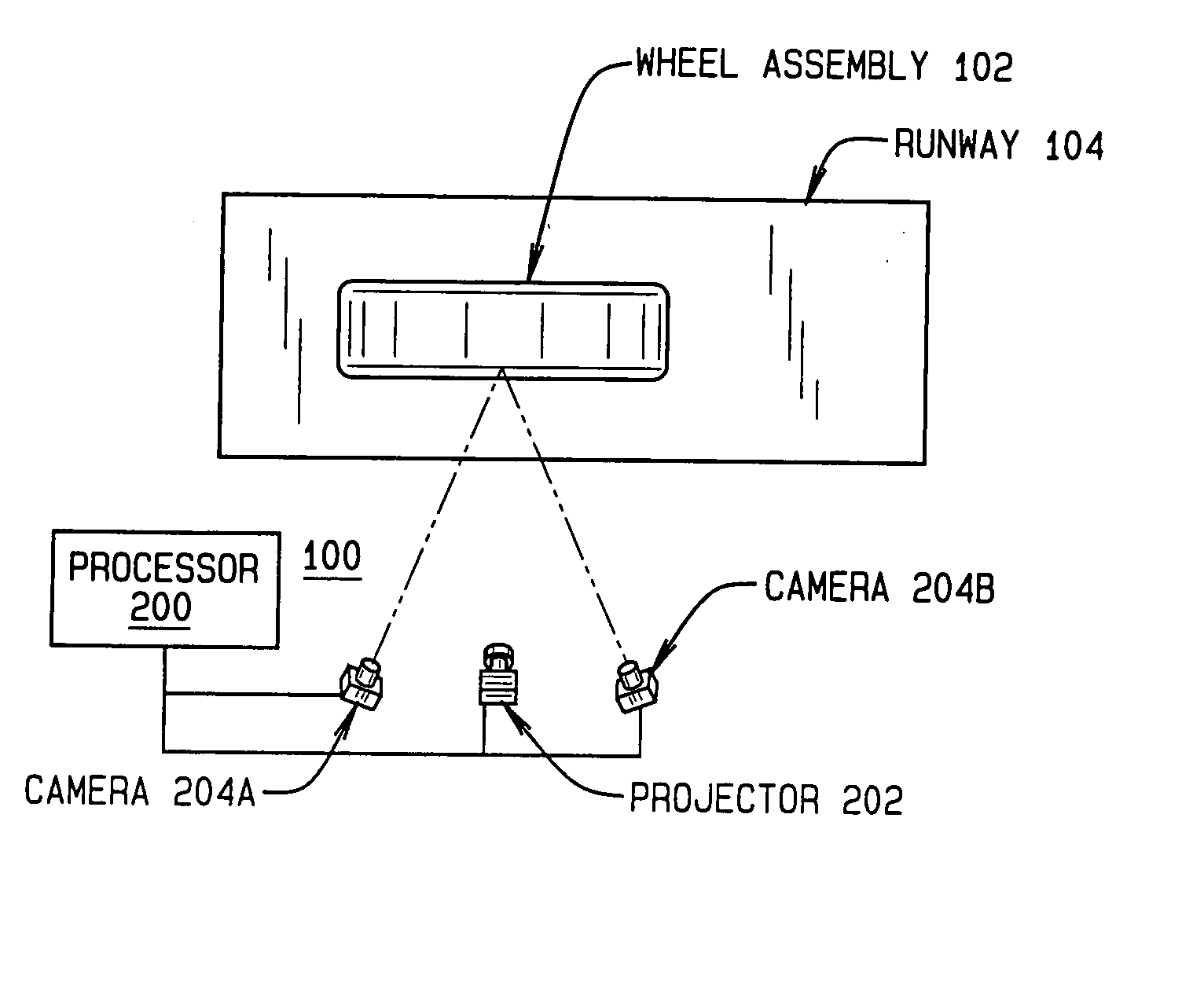
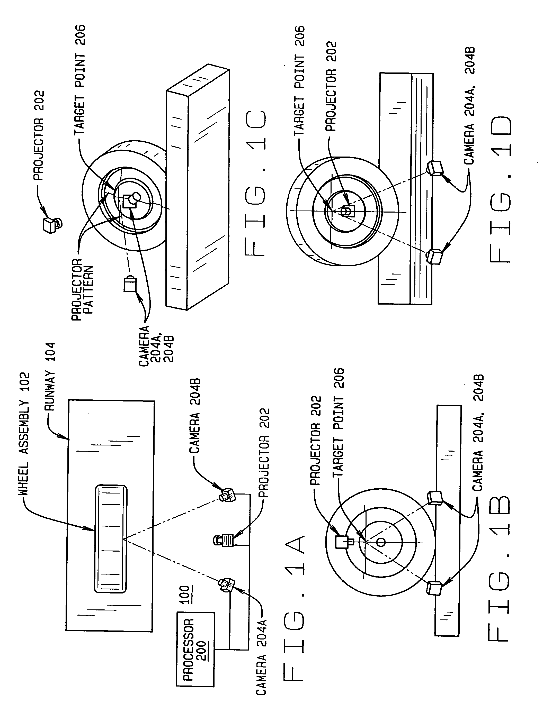
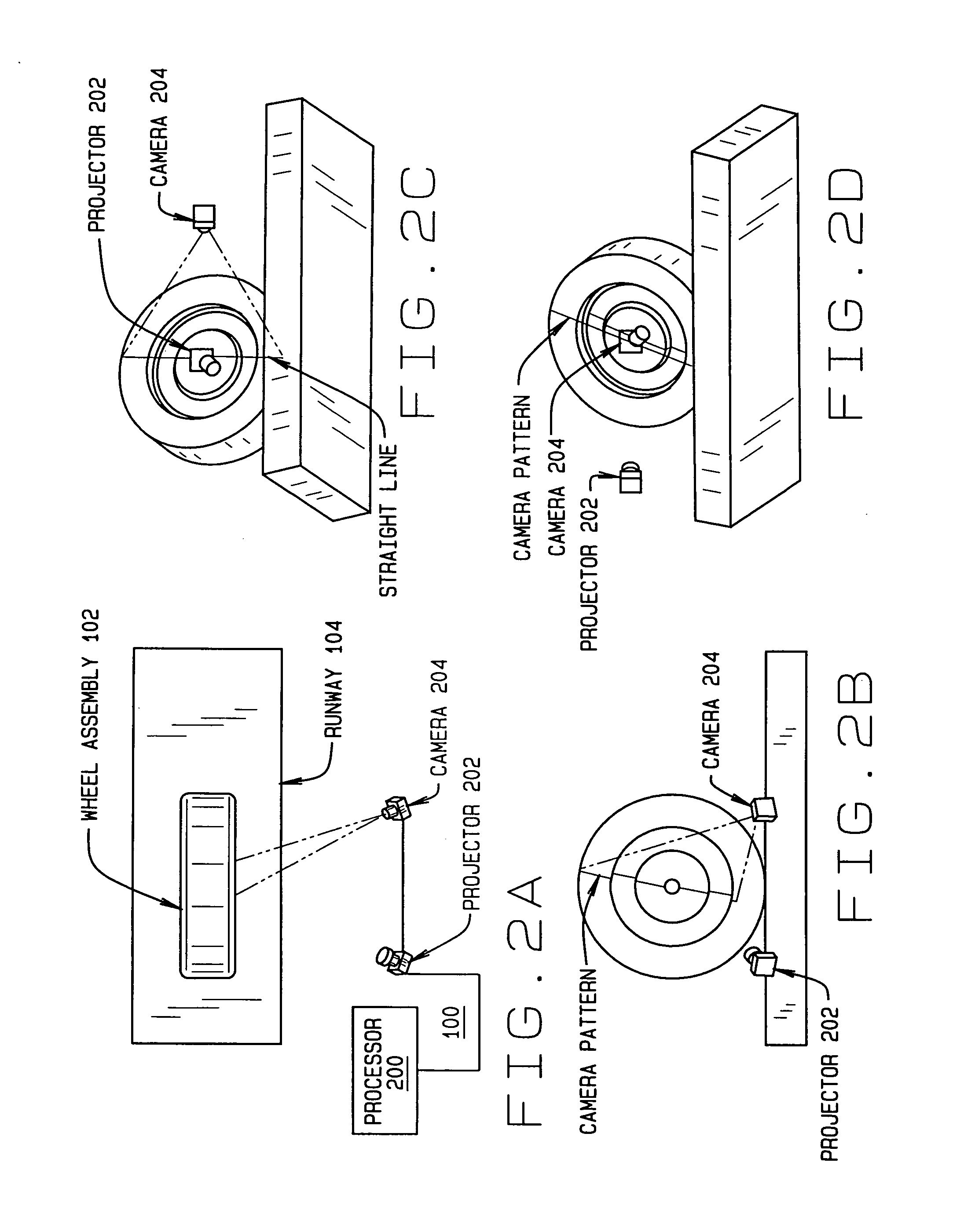
[0033] Turning to the Figures, and to FIGS. 1A-1D, 2A-2D, and 3A-3D in particular, components of a machine vision vehicle wheel alignment system 100 are shown in proximity to a single vehicle wheel assembly 102 disposed on a supporting surface, lift rack, or runway 104. Those of ordinary skill will recognize that the components of the vehicle wheel alignment system 100 described are understood to be duplicated where necessary for purposes of acquiring vehicle wheel alignment measurements from multiple wheel assemblies of a vehicle undergoing a vehicle wheel alignment service procedure, and that the configur...


PUM


Abstract

A machine vision vehicle wheel alignment system configured with at least one cameras for acquiring images of the wheels of a vehicle, and an associated light projectors configured to project a pattern image onto the surfaces of vehicle components such as vehicle wheel assemblies. Images of the projected patterns acquired by the camera, are processed by the vehicle wheel alignment system to facilitate a determination of the relative orientation and position of the surfaces such as wheel assemblies in three dimensional space, from which vehicle parameters such as wheel alignment measurements can be subsequently determined.

Description

CROSS-REFERENCE TO RELATED APPLICATIONS [0001] The present application is related to, and claims priority from, U.S. Provisional Patent Application Ser. No. 60 / 732,003 which was filed on Nov. 1, 2005, and which is herein incorporated by reference.STATEMENT REGARDING FEDERALLY SPONSORED RESEARCH [0002] Not Applicable. BACKGROUND OF THE INVENTION [0003] The present invention is related to machine vision vehicle wheel alignment systems configured to view an optical target associated with a vehicle wheel to determine vehicle wheel alignment angles, and in particular, to a machine vision vehicle wheel alignment system which includes an optical projection system adapted to project a target pattern onto a vehicle wheel to aid in the determination of vehicle wheel alignment angles. [0004] Conventional machine vision wheel alignment systems such as shown in U.S. Pat. No. 5,535,522 to Jackson and in U.S. Pat. No. 5,675,515 to January use predefined target structures which are physically mount...

Claims


Application Information

Patent Timeline
Patent Type & Authority Applications(United States)
IPC IPC(8): G01B5/00
CPCG01B11/2509G01B11/2513G01B11/2545G01B11/2755G01B2210/146G01B2210/28G01B2210/286
Inventor BURNS, LEIGH R. JR.DORRANCE, DANIEL R.COLARELLI, NICHOLAS J. IIISTREGE, TIMOTHY A.FRITON, GERALD E.SHYLANSKI, MARK S.VOELLER, DAVID A.
Owner HUNTER ENG
Why Eureka
Try Eureka