Method and apparatus for regeneration water

a water regeneration and water technology, applied in the direction of domestic cooling apparatus, defrosting, separation processes, etc., can solve the problems of difficult to determine whether or not the water regeneration is completed, difficult to increase the temperature to 373 k, and water becomes a problem, so as to shorten the regeneration time and efficiently reprocess the water

Active Publication Date: 2007-06-07
SUMITOMO HEAVY IND LTD
View PDF2 Cites 15 Cited by
  • Summary
  • Abstract
  • Description
  • Claims
  • Application Information

AI Technical Summary

Benefits of technology

[0015] It is therefore an object of the present invention to efficiently discharge water and shorten a regeneration time, thereby overcoming the aforementioned conventional problems.
[0025] According to the present invention, a water regeneration apparatus for discharging ice condensed in a portion cooled by a cryogenic refrigerator installed in a case to an outside of the case, includes: temperature increasing means for increasing a temperature of the portion in the case in which the ice is condensed to a melting point of the ice or higher to melt the ice; vaporizing means for vaporizing water generated by melting of the ice by performing rough evacuation to reduce a pressure of the portion in which the water is accumulated within a range in which the temperature and the pressure of the portion are prevented from reaching a freezing point of the water, performing buildup determination based on discharged moisture or gas when the evacuation is stopped, and repeating the water vaporization and the buildup determination until the water vanishes away; and evacuation means for discharging water vapor by further reducing the pressure at a time when the water is vaporized, thereby achieving the above object.

Problems solved by technology

In regeneration of the cryopump described above, regeneration of water becomes a problem.
However, it is difficult to increase the temperature to 373 K because of structures of the cryopump and the refrigerator.
In the conventional regeneration method (1) in which a purge gas is kept flowing so that water is saturated in the purge gas and is discharged from the inside of the cryopump, it is difficult to determine whether or not regeneration is completed.
Thus, it is necessary to make the gas flow for a long period of time so as to finish discharging of the water under a worst condition and therefore wasteful time is very long.
However, in the latter method (2), water is frozen during roughing by means of the dry pump.
Thus, water is not sufficiently discharged and the pressure is not reduced to the set value.
Therefore, a time required for regeneration becomes longer in some cases.

Method used


Image

  • Method and apparatus for regeneration water
  • Method and apparatus for regeneration water
  • Method and apparatus for regeneration water

Examples


Embodiment Construction

[0039] An exemplary embodiment of the present invention is now described in detail with reference to the drawings.

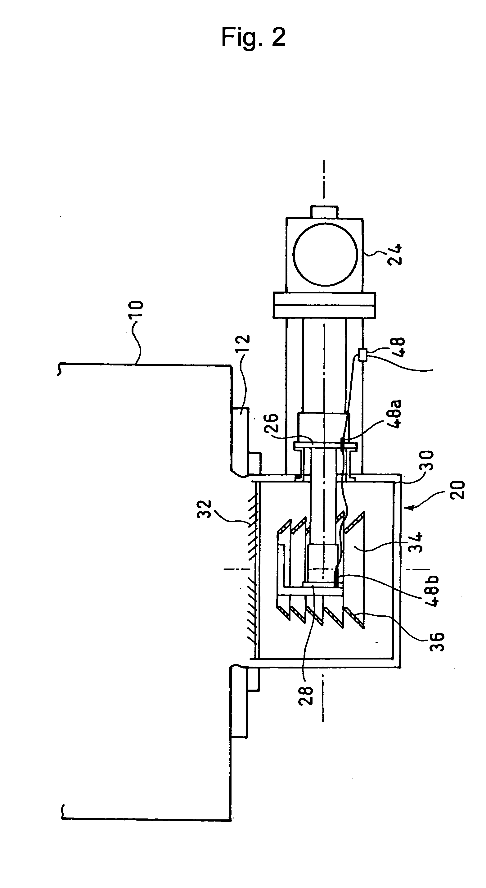
[0040]FIG. 5 shows an exemplary cryopump to which the exemplary embodiment of the present invention is applied. A heater 52 for the first stage 26 and a heater 54 for the second stage 28 are added to the structure shown in FIG. 2. The reference numeral 56 in FIG. 5 denotes a connector for a heater.

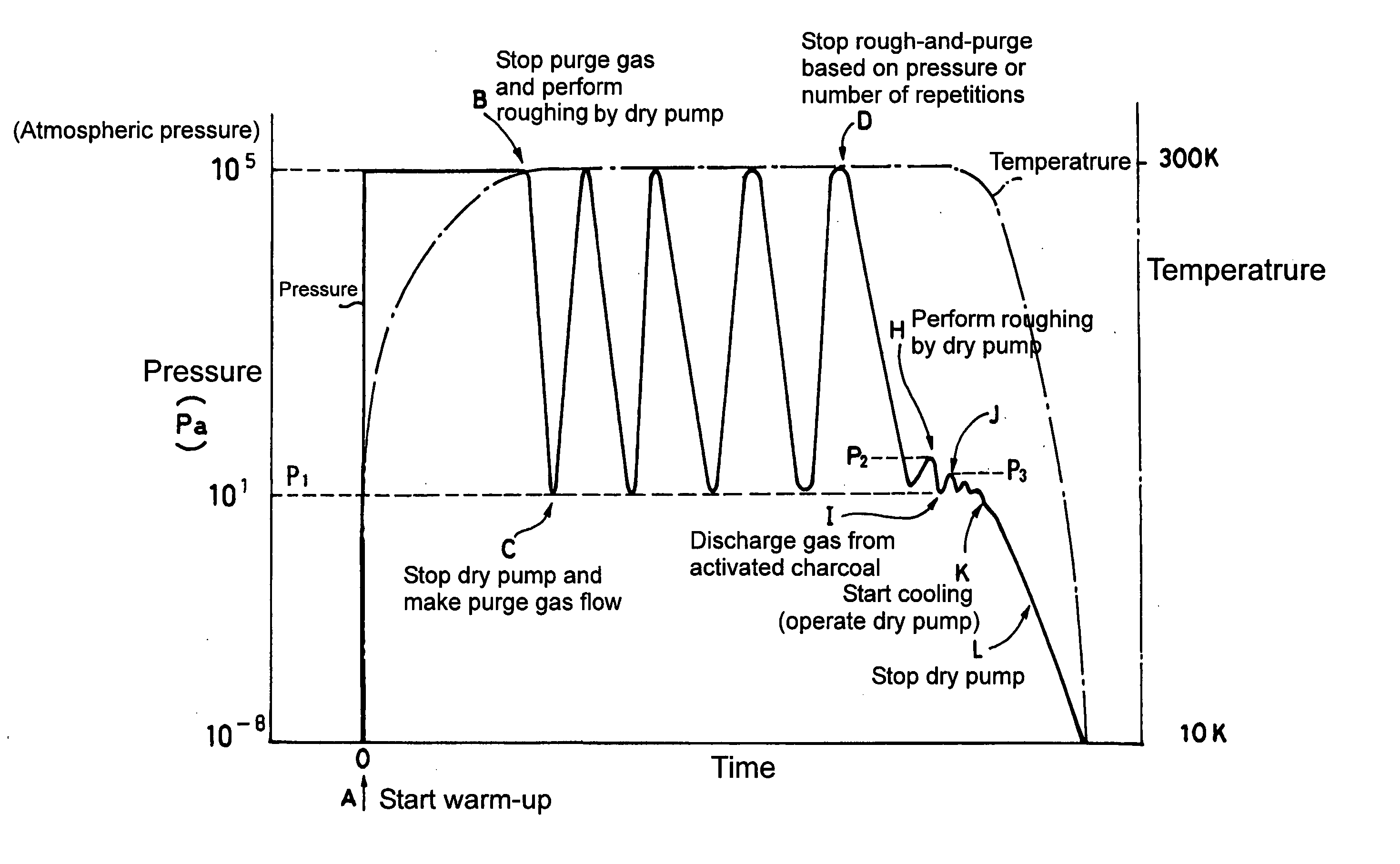
[0041] Regeneration of water according to the present invention is performed in a procedure shown in FIG. 6. Referring to FIG. 7, warm-up is started at Point A as in the conventional method. In the warm-up, while a temperature is increased by a reverse rotation or by the heaters 52 and 54, for example, N2 gas (purge gas) is made to flow in order to improve thermal conductivity with the outside of the case (Step 100 in FIG. 6). Then, a rough-and-purge cycle is started at Point B (step 110′ in FIG. 6). In this cycle, a lower limit of a pressure is set to a value higher than a l...


PUM

PropertyMeasurementUnit
pressureaaaaaaaaaa
freezing pointaaaaaaaaaa

Abstract

Ice condensed in a portion in a case in which a cryogenic refrigerator is installed, which is cooled by the cryogenic refrigerator, is melted by increasing a temperature of the ice to a melting point of the ice or higher. Then, while the temperature of the melted ice and a pressure thereof are kept to be equal to or higher than a freezing point of water, the pressure is reduced by rough evacuation so as to vaporize water. At a time at which the water is discharged, the pressure is further reduced so as to discharge water vapor. In this manner, regeneration of water is performed in accordance with a state of the water (i.e., a solid state, a liquid state, and a gas state), thereby shortening a regeneration time.

Description

TECHNICAL FIELD [0001] The present invention relates to a water regeneration method and a water regeneration apparatus. In particular, the present invention relates to a water regeneration method and a water regeneration apparatus for discharging ice condensed in a portion cooled by a cryogenic refrigerator installed in a case to the outside of the case, which are suitably used for discharging water that is condensed as ice on a cryopanel in a cryopump out. BACKGROUND ART [0002] A cryopump is conventionally used for evacuation of a vacuum chamber (that may be called as a process chamber) of a semiconductor manufacturing apparatus or the like in order to keep the inside of the vacuum chamber vacuum. [0003] An exemplary use of the cryopump described in Japanese Patent Laid-Open Publication No. 2000-274356 is shown in FIG. 1 (plan view) and FIG. 2 (vertical cross-sectional view). [0004] The cryopump 20 includes a two-stage GM (Gifford-McMahon) expansion type refrigerator 24 that works ...

Claims


Application Information

Patent Timeline
Patent Type & Authority Applications(United States)
IPC IPC(8): B01D8/00F25D21/00F25D21/06F04B37/08
CPCF04B37/08Y10S417/901F04B29/00
Inventor TSUYUKI, RYOSUKE
Owner SUMITOMO HEAVY IND LTD
Why Eureka
Try Eureka