
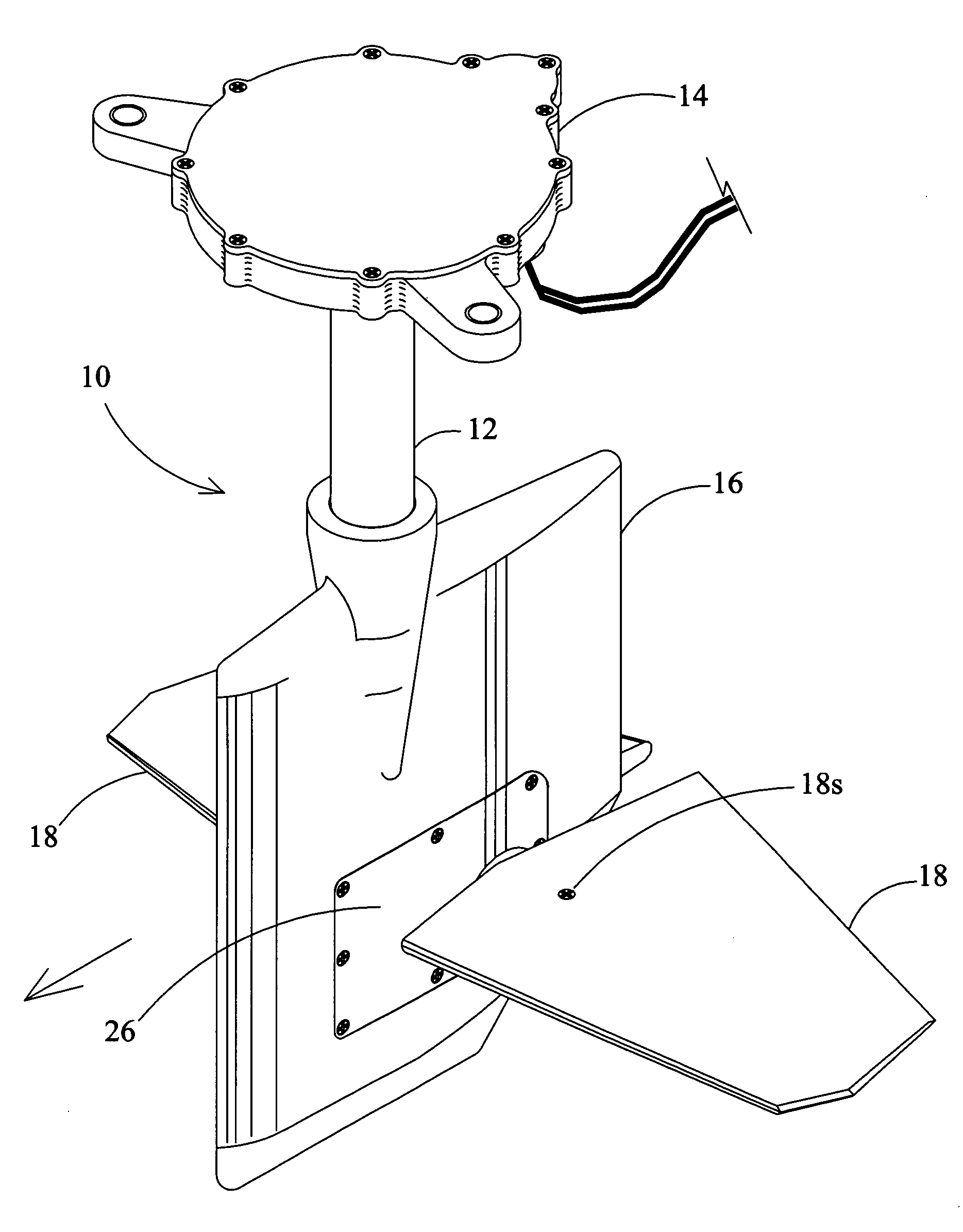
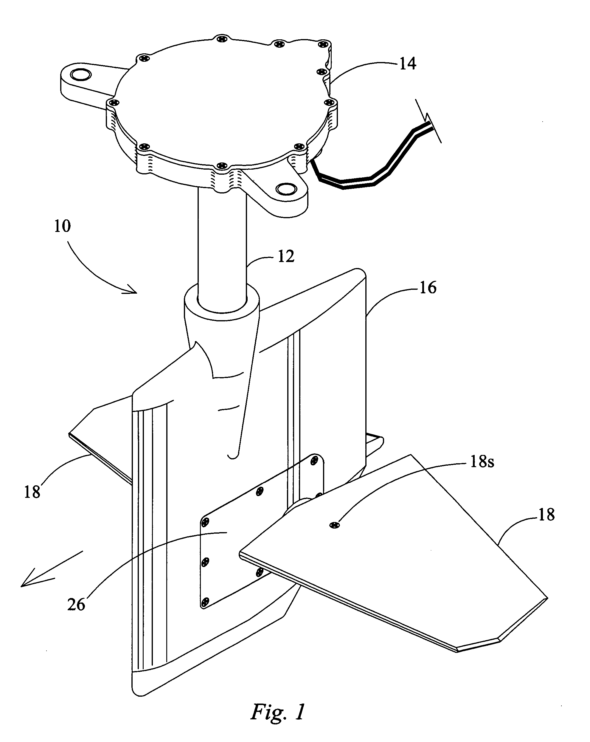
Boat rudder with integrated dynamic trim foils

Inactive Publication Date: 2007-06-07
WAVEFRONT TECH INC
View PDF8 Cites 40 Cited by
  • Summary
  • Abstract
  • Description
  • Claims
  • Application Information

AI Technical Summary

Benefits of technology

[0030] In at least one embodiment, the desired attitude is a setting to raise the stern of the boat relative to a neutral hull attitude that the hull sits at when not moving, to create a reduced wake size for use in waterskiing sports.

Problems solved by technology

In extreme cases, such as racing hydroplanes, this phenomenon, if not controlled can cause disastrous results, as it is not uncommon to see one of these boats flip over, end-to-end, during racing speeds.
This process is time-consuming, and can be particularly annoying when out in the water and waiting to empty the tank or bladder.
Therefore even after pumping all of the water out of the tank or bladder, the boat is still not necessarily as efficient in going through the water as it could be.
Thus, these solutions do not provide the ability to raise the stern higher than it would normal ride during propulsion if no trim forces were applied (neutral position), thereby also forcing the bow of the boat downward.
Chew's device is mounted to a keel and is therefore not easily adaptable to existing boats for modification thereof.
All of the adjustment mechanisms for the device are exposed to the environment and thus susceptible to corrosion and failure, not only from corrosion, but also by being fouled by seaweed, brush, or other environmental nuisances.
Further, by providing the trim adjusting mechanism to include the drum 45 engaging the steering post 15, this device experiences an undesirable effect when the boat is being turned via the steering post and rudder.
That is, when the leading edges of the trim plates are adjusted downwardly, the force of the water over the leading edges of the trim plates will make it difficult to return the trim plates to neutral (horizontal) because the trim plates are pivoted at the extreme rear ends thereof.
Similarly, when the leading edges of the trim plates are adjusted upwardly, the force of the water under the leading edges of the trim plates will make it difficult to return the trim plates to neutral (horizontal) because the trim plates are pivoted at the extreme rear ends thereof.

Method used


Image

  • Boat rudder with integrated dynamic trim foils
  • Boat rudder with integrated dynamic trim foils
  • Boat rudder with integrated dynamic trim foils

Examples


Embodiment Construction

[0044] Before the present apparatus and methods are described, it is to be understood that this invention is not limited to particular embodiments or components described, as such may, of course, vary. It is also to be understood that the terminology used herein is for the purpose of describing particular embodiments only, and is not intended to be limiting, since the scope of the present invention will be limited only by the appended claims.

[0045] Where a range of values is provided, it is understood that each intervening value, to the tenth of the unit of the lower limit unless the context clearly dictates otherwise, between the upper and lower limits of that range is also specifically disclosed. Each smaller range between any stated value or intervening value in a stated range and any other stated or intervening value in that stated range is encompassed within the invention. The upper and lower limits of these smaller ranges may independently be included or excluded in the range...


PUM


Abstract

A rudder and dynamic trim adjusting apparatus for a boat includes a rudder, a rudder shaft extending from the rudder and being rotatable about a longitudinal axis thereof to rotate the rudder, trim fins extending from the rudder, along at least one transverse axis transverse to the longitudinal axis, and a mechanism connected to the trim fins, and being operable, independently of rotation of the rudder shaft to rotate the trim fins about the at least one transverse axis. Methods of controlling an attitude of a boat hull are provided.

Description

CROSS-REFERENCE [0001] This application claims the benefit of U.S. Provisional Application No. 60 / 597,127, filed Nov. 11, 2005, which application is incorporated herein by reference, and to which we claim priority under 35 U.S.C. Section 119(e).FIELD OF THE INVENTION [0002] The present invention relates to a rudder for a boat, more particularly a rudder providing dynamically adjustable stabilization. BACKGROUND OF THE INVENTION [0003] In most, if not all propeller-driven power boats, the driving of the boat by the propeller tends to raise the bow of the boat and draw the stern downwardly, wherein variations in degree of this phenomenon may occur with variations in the amount of power applied, or speed of the propeller, among other variables, such as size of the propeller blades, depth in the water of the propeller, etc. In extreme cases, such as racing hydroplanes, this phenomenon, if not controlled can cause disastrous results, as it is not uncommon to see one of these boats flip o...

Claims


Application Information

Patent Timeline
IPC IPC(8): B63H25/02
CPCB63B39/06B63B39/061B63B39/062B63H25/381B63H25/382
Inventor WALKER, JEFF
Owner WAVEFRONT TECH INC
Learn More