Dye sensitized solar cells having blocking layers and methods of manufacturing the same

a solar cell and sensitized technology, applied in the direction of capacitors, solid-state devices, electrolytic capacitors, etc., can solve the problems of increased electrons and ions traveling a greater distance, disadvantageous increase in the thickness of the semiconductor film, and short circuit between electrodes

Inactive Publication Date: 2007-06-07
GENERAL ELECTRIC CO
View PDF6 Cites 43 Cited by
  • Summary
  • Abstract
  • Description
  • Claims
  • Application Information

AI Technical Summary

Benefits of technology

[0006] Embodiments of the present invention may ad

Problems solved by technology

One problem associated with solar cells is electrical shorting between electrodes.
However, the thicker the semiconductor film, the greater the distance the electrons and ions may travel to reach an electrode.
Although longer light paths may be desirable to facilitate greater light absorption, the cur

Method used


Image

  • Dye sensitized solar cells having blocking layers and methods of manufacturing the same
  • Dye sensitized solar cells having blocking layers and methods of manufacturing the same
  • Dye sensitized solar cells having blocking layers and methods of manufacturing the same

Examples


Embodiment Construction

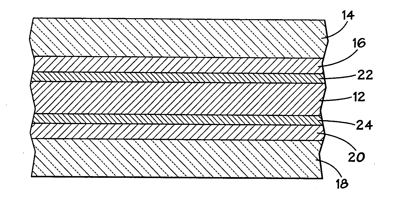
[0022]FIG. 1 illustrates an exemplary embodiment of a dye-sensitized solar cell 10, in accordance with embodiments of the present invention. The solar cell 10 may be fabricated by implementing any one of a number of techniques and using a variety of materials, as can be appreciated by those skilled in the art. The solar cell 10 includes an active layer 12 arranged between a first substrate 14 and a second substrate 18. The substrate 14 is transparent to allow impinging light to pass through the substrate 14. As used herein, “transparent” refers to a material allowing a total transmission of at least about 50%, preferably at least about 80% or higher, of visible light (i.e., having a wave length in the range from about 400 nm to about 700 nm).

[0023] Further, in accordance with one exemplary embodiment, the substrate 14 is generally thin and flexible, having a thickness in the range of approximately 0.25-50.0 mils, and preferably in the range of approximately 0.5-10.0 mils. As used h...


PUM


Abstract

A solar cell having at least one hole blocking layer and at least one electron blocking layer, and methods of fabricating such devices. Specifically, a hole blocking layer is disposed between a first electrode of the solar cell and the active layer. Further, an electron blocking layer is disposed between a second electrode and the active layer. The solar cell may be formed by fabricating an anode component and a cathode component and laminating the anode component and the cathode component together.

Description

BACKGROUND OF THE INVENTION [0001] Photovoltaic systems are implemented to convert light energy into electricity for a variety of applications. Power production by photovoltaic systems may offer a number of advantages over conventional systems. These advantages may include, but are not limited to, low operating costs, high reliability, modularity, low fabrication costs, and environmental benefits. As can be appreciated, photovoltaic systems include a number of photovoltaic devices, commonly known as “solar cells,” so named for their ability to produce electricity from sunlight. [0002] Conventional solar cells convert light into electricity by exploiting the photovoltaic effect that exists at semiconductor junctions. Accordingly, conventional solar cells generally implement active semiconductor layers to produce electron current. The semiconductor layers generally absorb incoming light to produce excited charge carriers. In addition to the semiconductor layers, solar cells generally ...

Claims


Application Information

Patent Timeline
IPC IPC(8): H01L31/00
CPCH01G9/2031H01G9/2059H01G9/2072H01G9/2095H01L27/302H01L51/0024H01L51/0086H01L51/0097H01L51/4226Y02E10/542Y02E10/549H10K30/57H10K71/50H10K85/344H10K30/151H10K77/111
Inventor GUI, JOHN YUPENGMANIVANNAN, VENKATESANYAKIMOV, AHARONJANORA, KEVIN
Owner GENERAL ELECTRIC CO
Why Eureka
Try Eureka