

Anti-shock device
a technology of anti-shock device and anti-shock plate, which is applied in the direction of shock absorption, shock proofing, machine supports, etc., can solve the problems of no vertical vibration use, skyscrapers are faced with potential dangers, and reduce horizontal vibration, so as to reduce the size of the anti-shock device and eliminate vibrations
- Summary
- Abstract
- Description
- Claims
- Application Information
AI Technical Summary
Benefits of technology
Problems solved by technology
Method used
Image

Examples
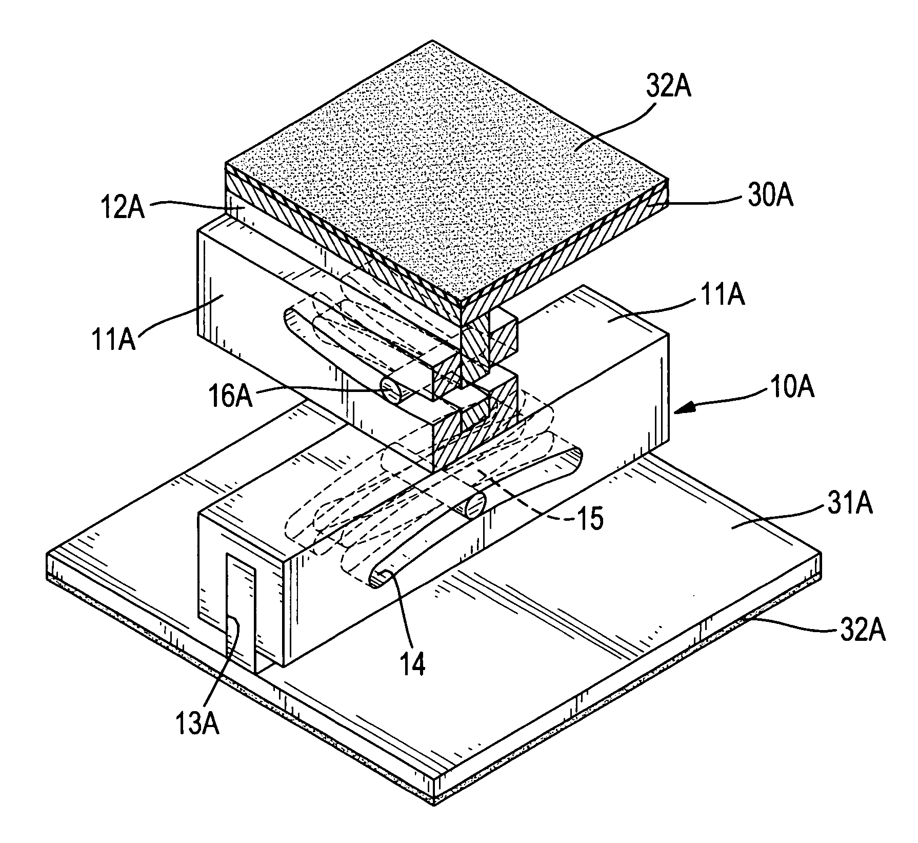
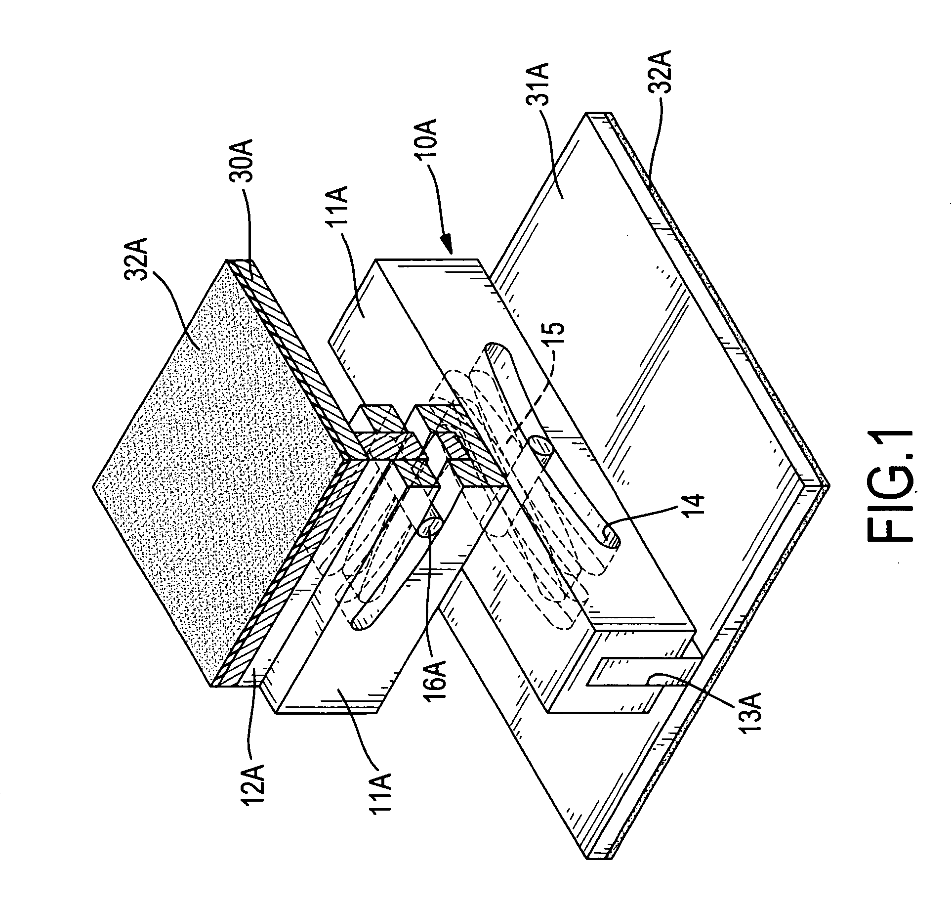
first embodiment
[0031] With reference to FIG. 4, the rolling shaft (16A) in the first embodiment is replaced by a rolling shaft (16B) that has a smaller diameter than the rolling shaft (16A). In this embodiment, the energy dissipation member (20) is a dampening layer (21) covering inner walls of the outer curved rails (14). In addition, the dampening layer (21) can also cover inner walls of the inner curved rails (15).
[0032] With reference to FIG. 5, the inner seat (12A) is replaced by an inner seat (12C) that is thinner than the inner seat (12A), so the dampening layer (21) is filled in a space between the inner seat (12C) and an inner wall of the slot (13A).
[0033] With reference to FIG. 6, in a sixth embodiment of the anti-shock device, the rolling shaft (16A) in the first embodiment is replaced by a rolling shaft (16C) that is longer than the rolling shaft (16A), so two ends of the rolling shaft (16C) extend out of sidewalls of the slotted seat (11A). The energy dissipation member (20) is a pad...
eighth embodiment
[0039] In the eighth embodiment, the two sliding members (10A) can also be replaced by two modified sliding members (10C).
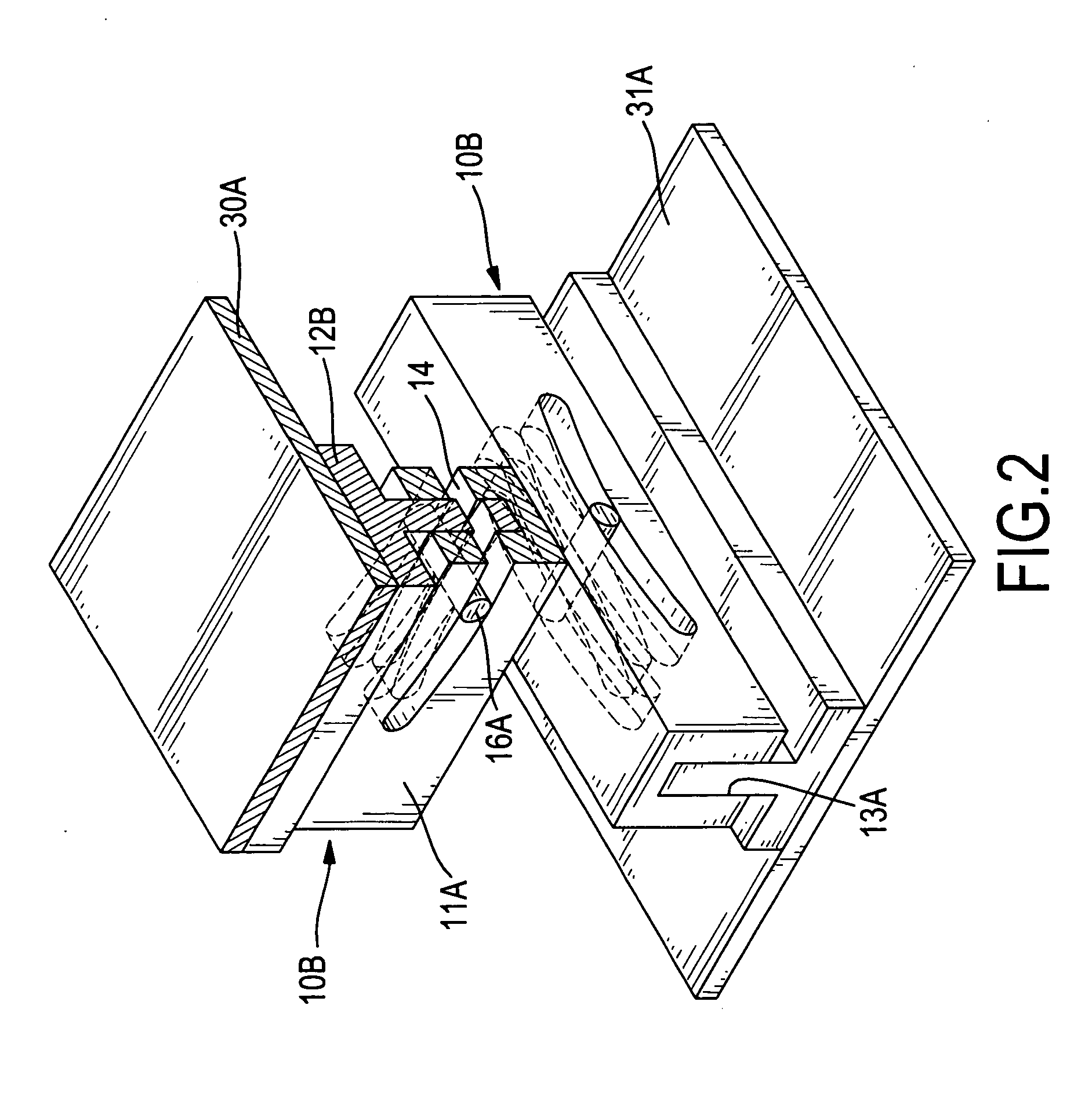
second embodiment
[0040] It is also applicable that the two sliding members (10A) can be turned over, with the two inner seats (12A) contacting the modified sliding member (12C), or the modified sliding member is turned over, too. In addition, the inner seats (12C), (12A) can also be replaced by the T-shaped seat (12B) in the
[0041] The energy dissipation member (20) is also applicable in the eighth embodiment.
[0042] With reference to FIG. 9, the anti-shock device is similar to the eighth embodiment, wherein the modified sliding member (12C) is replaced by a modified sliding member (10D), which is orthogonally placed on the two sliding members (10A). The modified sliding member (10D) is comprised of a slotted seat (11B), an inner seat (12D) and more than one rolling shaft (16A). Two rolling shafts (16A) are applied in this ninth embodiment.
[0043] The slotted seat (11B) has a slot (13B) defined longitudinally in a top face or a bottom face, and two sets of outer curved rails (14) are defined in oppos...
PUM
 Abstract
Description
Claims
Application Information