
Horn mass spectrometer having blade deflectors

a mass spectrometer and horn technology, applied in mass spectrometers, stability-of-path spectrometers, separation processes, etc., can solve the problems of remarkable sensitivity loss, 180-fold sensitivity loss, and practicability inability to use, and achieve high capacitive loading, poor vacuum capacity, and cost-effective fabrication

Inactive Publication Date: 2007-06-07
HAGERMAN JAMES G
View PDF5 Cites 0 Cited by
  • Summary
  • Abstract
  • Description
  • Claims
  • Application Information

AI Technical Summary

Benefits of technology

[0007] In accordance with the present invention, a novel construction is provided for the deflection electrodes of a rotating electric field ion mass spectrometer, wherein the deflection electrodes are formed as an array of blade elements arrayed radially and circumferentially about the ion axis and extending along its longitudinal length. In particular, a hyperbolic helical horn mass spectrometer (3HMS) is formed with such an array of blade elements aligned in an orthogonal fashion to replicate the same shape of hyperbolic electrode surfaces. When a sufficient number of blades are used, the resultant electric field exhibits a nearly identical constitution as using hyperbolic wall surfaces for the deflection electrodes. The orthogonal blade design solves the problems of costly fabrication, high capacitive loading and poor vacuum capacity, as compared to using cylindrically symmetric, hyperbolic wall surfaces for the deflection electrodes.

Problems solved by technology

Unfortunately, the REFIMS device heretofore has had severe inherent problems relating to ion entrance angle and sensitivity that have made it practically unusable.
Constructing a device with these limitations is possible, but the loss of sensitivity is remarkable.
If this tolerance is off by + / −1 degree, it means a sensitivity loss of 180 times, even before filtering takes place.
However, fabrication of the assembly can prove to be costly, requiring precision 3-axis machining and polishing.
Moreover, it also has drawbacks of high capacitive loading and poor vacuum capacity.

Method used


Image

  • Horn mass spectrometer having blade deflectors
  • Horn mass spectrometer having blade deflectors
  • Horn mass spectrometer having blade deflectors

Examples


Embodiment Construction

[0017] In the following detailed description of the invention, certain preferred embodiments are illustrated providing certain specific details of their implementation. However, it will be recognized by one skilled in the art that many other variations and modifications may be made given the disclosed principles of the invention.

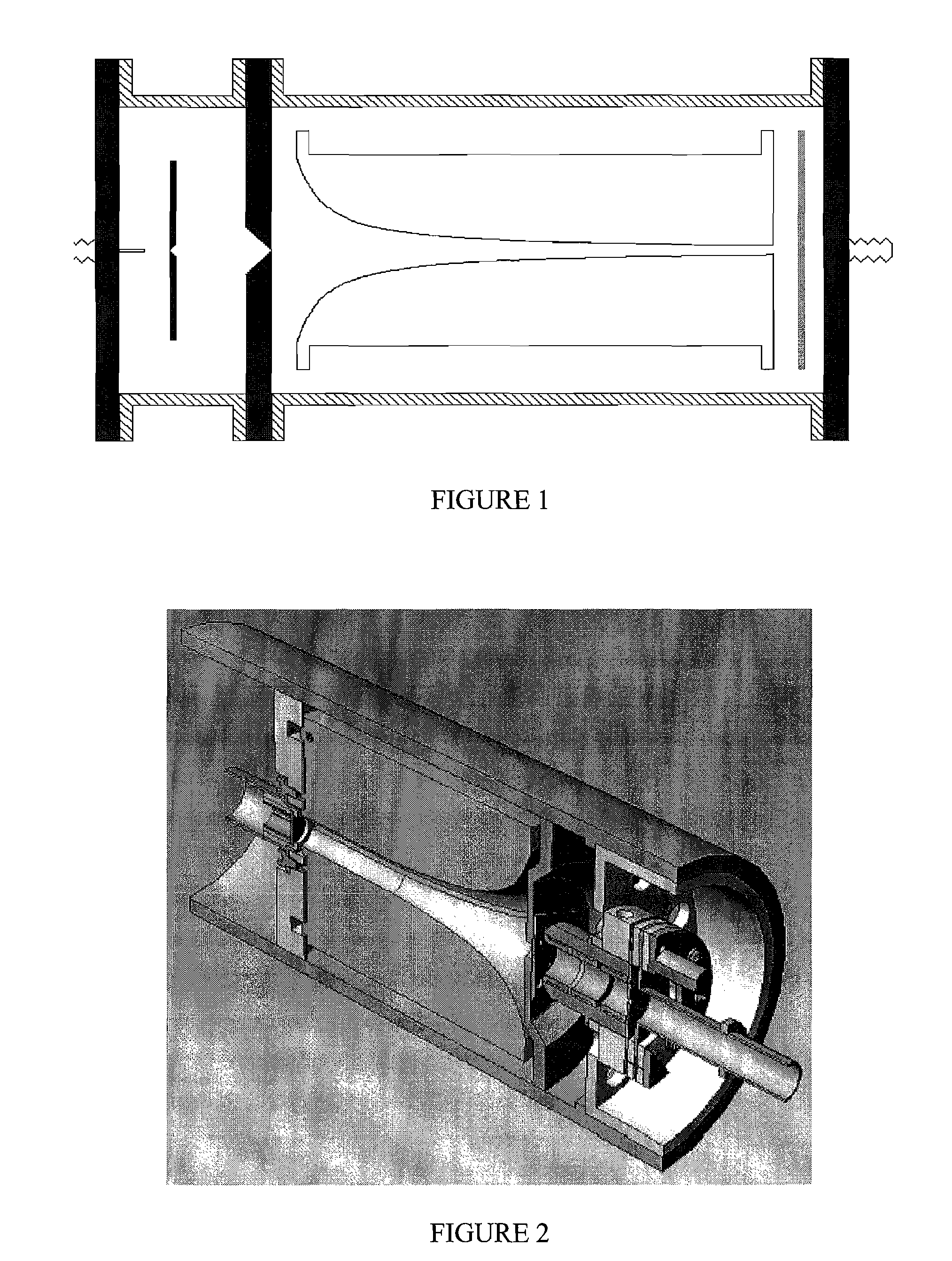
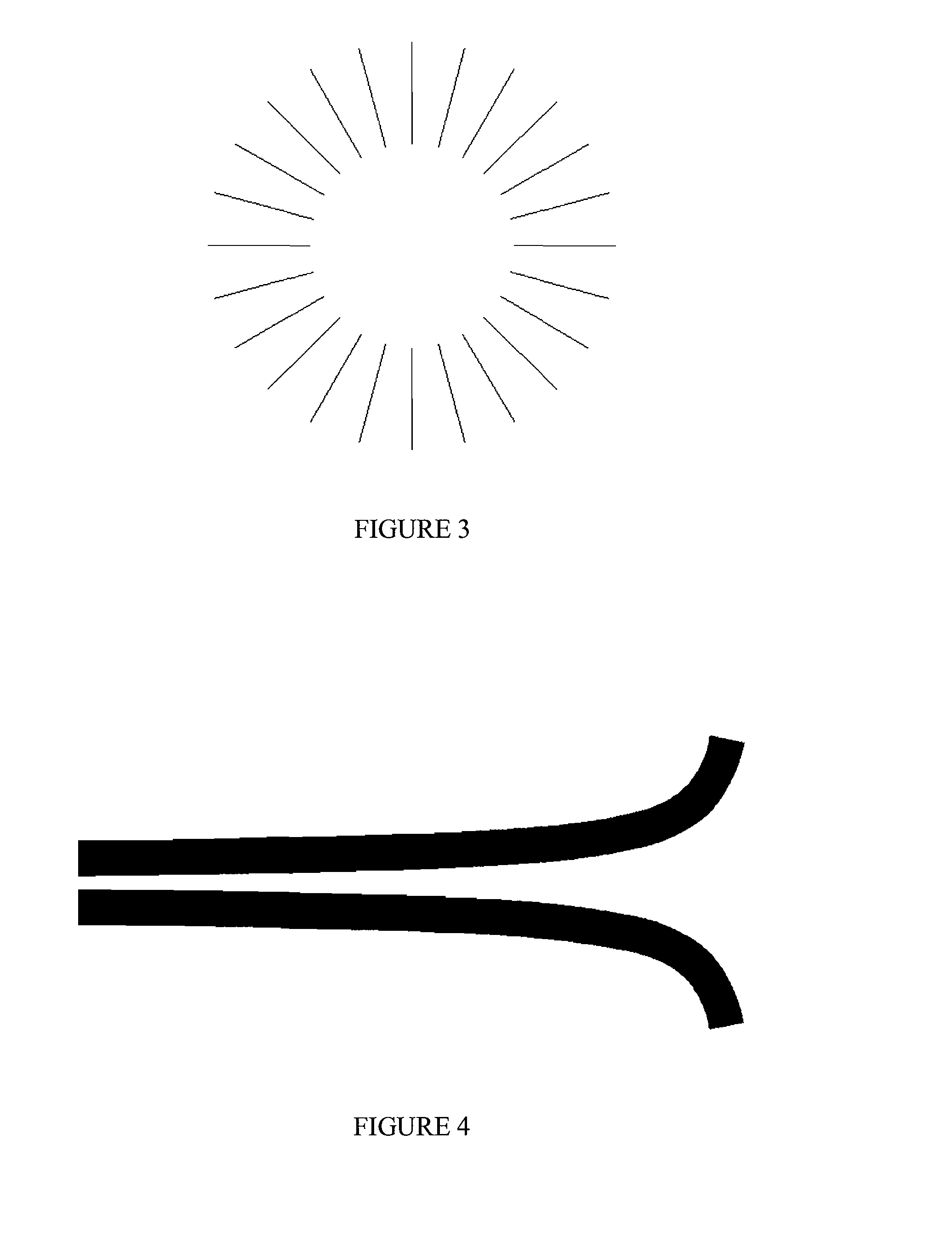
[0018]FIG. 3 shows a schematic end-on view of the improved “blade array” construction for the deflector electrodes of a hyperbolic helical horn mass spectrometer (3HMS) unit in accordance with the present invention. The blades are arrayed radially and circumferentially about the ion axis of the horn extending along its longitudinal length. If an infinite number of blades are used, the inner surfaces of the blade would form an exact replica of the hyperbolic wall surfaces of the prior design shown in FIG. 2. It is found in the present invention that use of a sufficient number of blade elements can provide an electric field similar to using an infinite number...


PUM


Abstract

An improved design for a rotating electric field ion mass spectrometer has deflection electrodes formed as an array of blade elements arrayed radially and circumferentially about an ion axis of the mass spectrometer. The blade elements are formed as flat metal pieces having inner edges shaped in a hyperbolic curve. When a sufficient number of blades are aligned orthogonally to form a horn shape along an ion axis of a hyperbolic helical horn mass spectrometer, the resultant electric field approximates that of using hyperbolic wall surfaces for the deflection electrodes. The blade array design reduces the cost of fabrication, capacitive loading, and vacuum capacity as compared to using cylindrically symmetric, hyperbolic wall surfaces for the deflection electrodes.

Description

[0001] This U.S. patent application is a continuation-in-part of co-pending U.S. patent application Ser. No. 11 / 297,238 of the same inventor filed on Dec. 7, 2005, entitled “Hyperbolic Horn Helical Mass Spectrometer”TECHNICAL FIELD [0002] This invention generally relates to an improvement for a rotating electric field ion mass spectrometer (REFIMS), and more particularly, to one which reliably handles the ion input beam with better tolerance for entrance angle and sensitivity. BACKGROUND OF INVENTION [0003] A prior type of rotating electric field ion mass spectrometer (REFIMS) has an analyzer cell with an entrance end, four spaced-apart longitudinal deflector walls to which time-dependent phased RF potentials are applied, and a detector at its target end. This type of REFIMS cell is described in U.S. Pat. No. 5,726,448 issued on Mar. 10, 1998, to S. J. Smith and A. Chutjian, which is incorporated by reference. The time-dependent RF potentials applied to the cell walls create an RF f...

Claims


Application Information

Patent Timeline
Patent Type & Authority Applications(United States)
IPC IPC(8): H01J49/42
CPCH01J49/421
Inventor HAGERMAN, JAMES G.
Owner HAGERMAN JAMES G
Learn More